COVO KNOWLEDGE
Press Brake Bend Development: Flat Length, Deduction and Hem Dimensions
Published:
Last reviewed:
Learn how A and B leg dimensions, sheet thickness, bend deduction, press-line position and hem allowances connect before a press brake job reaches production.
A flat blank is the starting point for every accurate press brake part. This COVO guide explains how to connect finished leg dimensions, sheet thickness, bend deduction, press-line position and hem dimensions before the first cycle.
The training pages behind this article use a simple A and B section to explain pressed-edge development. We have redrawn the technical diagrams in English and kept the original calculation relationships visible. Use the formulas as documented starting points, then verify them with the actual punch, die, material and first piece.


What is press brake bend development?
Press brake bend development is the process of converting the required formed dimensions into the flat length that must be cut before bending. The calculation must account for the material consumed or released in the bend region. If the blank is too long, the finished legs can exceed the drawing. If it is too short, the part may not reach the required flange or hem dimension.
In the examples, A and B represent the straight leg dimensions of a bent section, while t is the sheet thickness. The correct relationship also depends on the drawing datum: inside dimension, outside dimension, bend line, press line or controller coordinate.
The 0.4t starting convention for a pressed edge
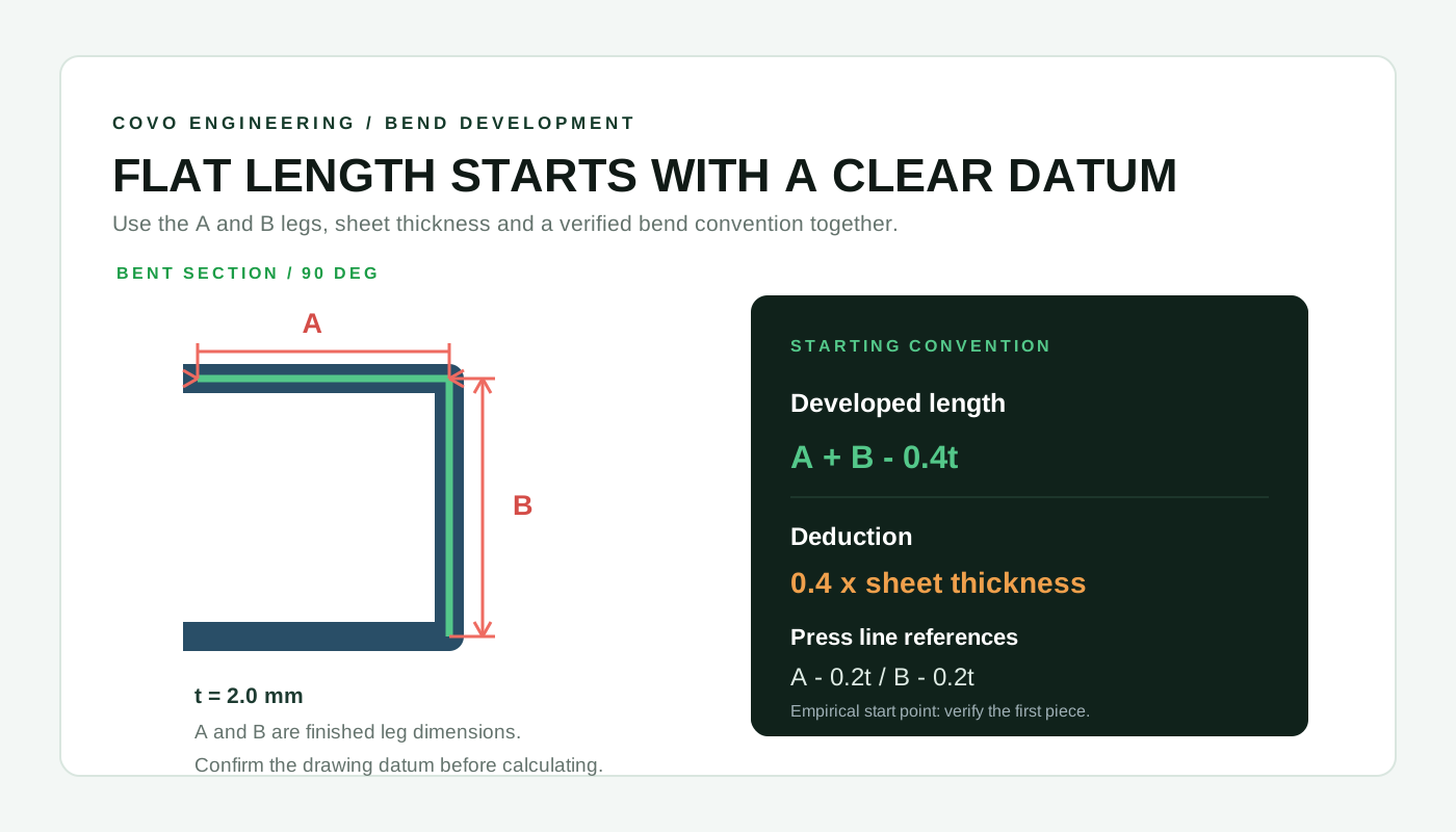
The first training example expresses the developed length as:
Deduction = 0.4 × sheet thickness
For a sheet thickness of 2.0 mm, the illustrated deduction is 0.8 mm. The same convention places the press-line references at approximately A - 0.2t and B - 0.2t. These values make the drawing logic easy to communicate, but the factor 0.4 is an empirical starting value rather than a universal constant.
Material strength, actual thickness, inside radius, die opening, punch nose, hemming method and machine condition can move the result. When the part is critical, cut a controlled test blank, make the first bend, measure the released part and update the approved setup value.
An alternative bend compensation expression
The next training page presents the same development problem with a different deduction symbol:
gamma = 2t - BA90
In this training convention, gamma is the press-brake bend compensation.
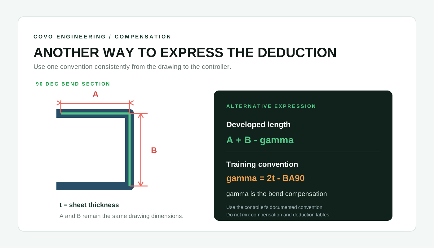
The important production lesson is consistency. One controller or shop table may use bend allowance, another may use bend deduction, and a third may display a compensation value. They can describe related geometry without being interchangeable fields. Record the convention next to the tool system, material and inspection method so an operator does not combine a bend allowance from one table with a deduction from another.
Press line and bend-line position
The press line is the practical reference used to locate the bend on the flat blank. In the supplied convention, each leg is reduced by approximately 0.2t from the finished leg reference. The line is useful only when its datum is clear and repeatable.
Do not assume that a press line equals the backgauge display or the X-axis value on every machine. Confirm whether the controller expects an outside dimension, an inside dimension, a bend-line coordinate, an L value, an X-axis position or a value that already includes compensation. Tool centerline, mounting height and die opening also affect how the number is used.
Right-angle size versus hem size
The later training diagram compares a right-angle section and a pressed hem made from the same bend-line condition. Its practical rule is:
When the final hem dimension must be larger, allow approximately 0.6t in the remaining pre-hem dimension.
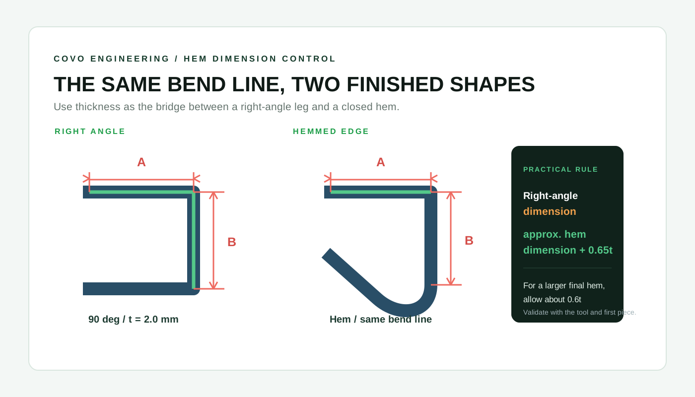
These relationships are useful when a drawing contains both open 90-degree bends and closed edges. They help the engineer decide where to place the pre-hem bend and how much material remains after the hemming operation. The actual allowance still depends on the punch and die profile, material, thickness, angle, flattening method and the final inspection datum.
A reliable bend-development workflow
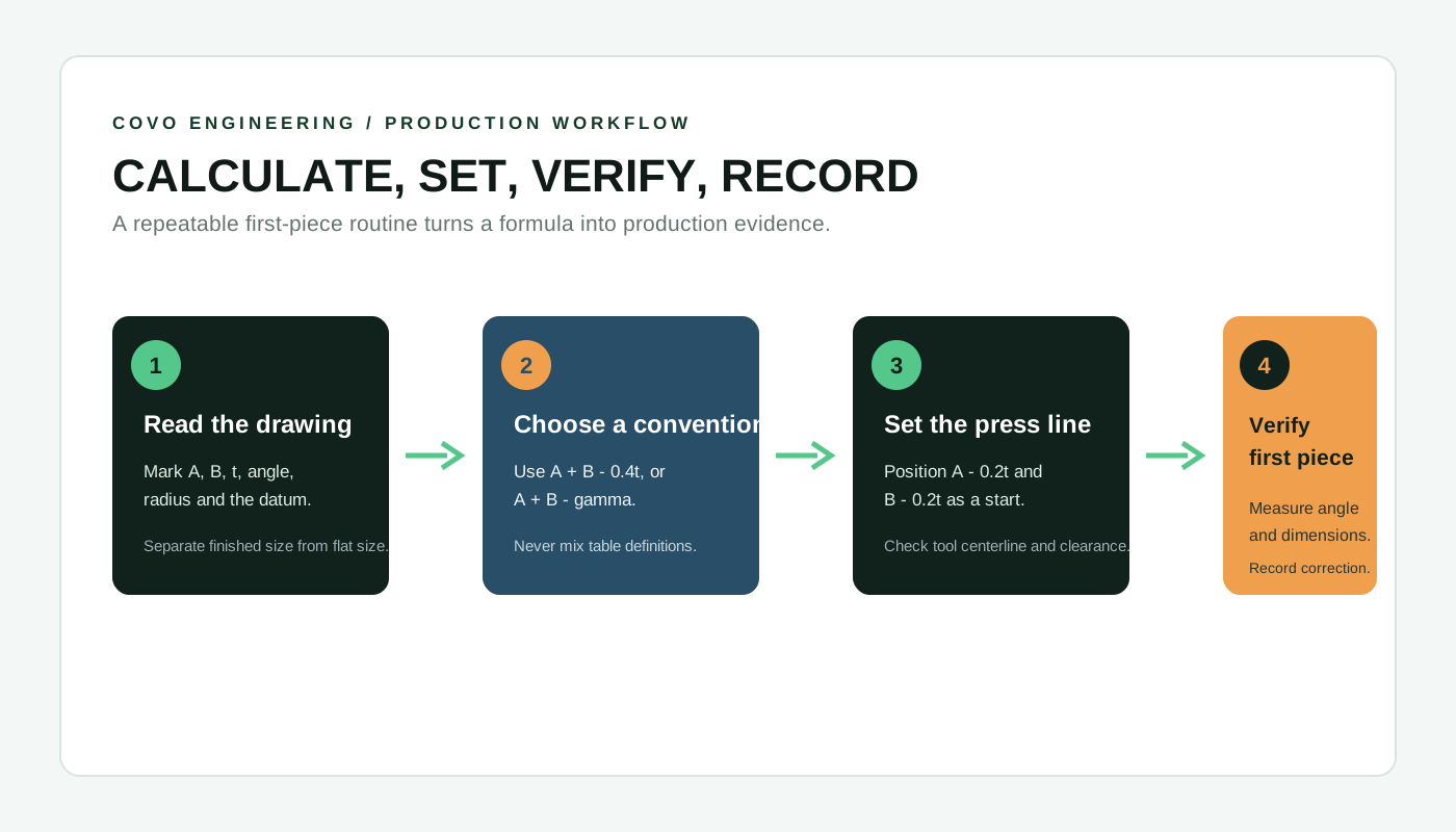
- Read the drawing: mark A and B dimensions, sheet thickness, angle, inside radius, hem size and the surface that will be inspected.
- Identify the datum: decide whether the critical dimension is measured inside, outside, from the bend line or from a controller coordinate.
- Choose one convention: use the approved 0.4t starting method or the documented gamma compensation method for the machine and material family.
- Set the press line: translate the finished leg dimensions into the flat blank using the same datum used by the program and setup sheet.
- Check the tooling: confirm system, punch profile, die opening, working height, clearance, hemming sequence and rated load.
- Verify a first piece: measure angle, A/B legs, outside or inside dimensions and hem size after the material has relaxed.
- Record the correction: keep the actual blank length, tool models, material data, controller value and inspection result for the next run.
Common calculation mistakes
- Using a universal 0.4 factor: treat it as a starting point, not a guaranteed result for every material and tool.
- Mixing bend allowance and bend deduction: use the symbols and signs defined by the same calculation table or controller.
- Ignoring actual thickness: nominal material labels do not always equal the measured sheet thickness.
- Measuring the wrong face: inside, outside and bend-line dimensions are different datums.
- Applying an open-bend value to a hem: hemming adds a separate forming step and needs its own clearance and size check.
- Skipping the tool check: die opening, punch radius and tool height change material flow and available clearance.
Connect development calculations to tooling selection
Flat-length accuracy is easier to repeat when the tool interface and working profile are known. COVO supplies system-matched tooling for AMADA, TRUMPF, WILA, LVD and BYSTRONIC systems, together with forming tools, mark-free bending and radius tools for profiles that cannot be handled by a standard set.
For a repeat job, compare the development value with the selected tool, material, bend sequence and inspection result. COVO can also review a hem, return flange or special formed edge when the drawing dimension is difficult to translate into a stable press-line position. The Bend Deduction Calculator can provide a useful starting point, but the approved production value should come from the actual setup.
Frequently asked questions
What is the basic pressed-edge flat-length formula?
In the training convention covered here, the starting formula is developed length = A + B - 0.4t. The 0.4t term is an empirical deduction and should be calibrated against the actual tool, material and first piece.
What does gamma represent in bend development?
In the alternative convention shown, gamma represents bend compensation and is expressed as gamma = 2t - BA90. The exact definition must follow the controller or calculation table used for the job.
How is a right-angle dimension related to a hem?
The supplied training relationship is approximately right-angle dimension = hem dimension + 0.65t. If the final hem must be larger, allow roughly 0.6t in the remaining pre-hem dimension, then validate the result with the selected tooling.
Can these formulas be used for every material?
No. They are practical starting conventions. Material strength, actual thickness, inside radius, die opening, springback, surface requirements and the hemming operation can change the result. Use a first piece and keep the measured correction with the setup.
Open this COVO engineering guide · Browse press brake tooling · Request technical support