COVO KNOWLEDGE
Press Brake Bend Line Explained: L, X and Bend Deduction
Published:
Last reviewed:
Learn how the press brake bend line connects tooling, outside dimensions, bend deduction, backgauge position and controller fields such as L or X.
A press brake program can show an angle, a backgauge value or a field called L. The finished part, however, is controlled by the relationship between the tool centerline, the bend line, the material thickness and the bend deduction. This COVO guide explains that relationship in practical terms.
The reference training pages use a simple 90° example to show why a bend line should be treated as a manufacturing datum. Once the punch and die, material thickness, angle and process conditions are defined, the bend line gives the operator a repeatable way to connect the drawing dimension to the machine setup.

What is a press brake bend line?
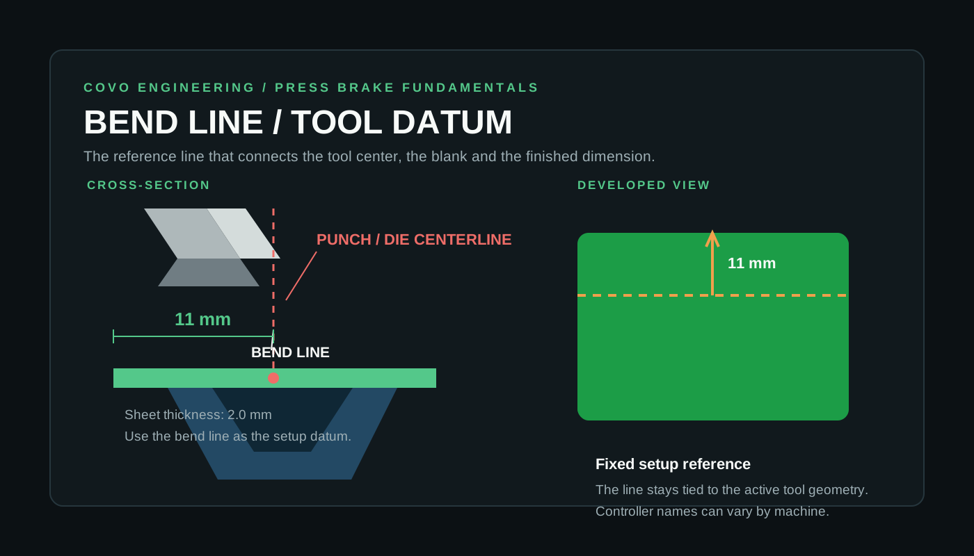
A bend line is the reference line used to locate the bend on the blank and to describe the resulting formed dimension. In a press brake cross-section, it is associated with the active punch and die centerline where the sheet is being formed. On a drawing, it identifies where the material should change direction. On the machine, it becomes a datum for positioning the sheet and checking the result.
The bend line is not simply the visible edge of the punch, and it is not automatically the same as the backgauge value. The actual meaning depends on the machine's coordinate convention, the selected tooling and whether the program uses an outside dimension, a bend-line position, an L value or an X-axis reference.
That is why the bend line should be written down together with the tool profile, material thickness, bend angle and inspection convention. A value without its datum can look precise while still producing the wrong flange.
Why the bend line matters more than a single controller number
When the angle, punch radius, die opening, material thickness and process method are fixed, the bend line is the dimension that connects the flat blank to the formed part. If the bend line is moved, the resulting outside dimension changes even when the press brake uses the same angle and the same tooling.
This is also why a machine input should not be copied from one press brake to another without checking the controller convention. Two machines may display similar fields but use different datums. One may ask for a bend-line position, another may calculate an X-axis position, and a third may ask for a formed or outside dimension.

A practical 90° bend-line calculation
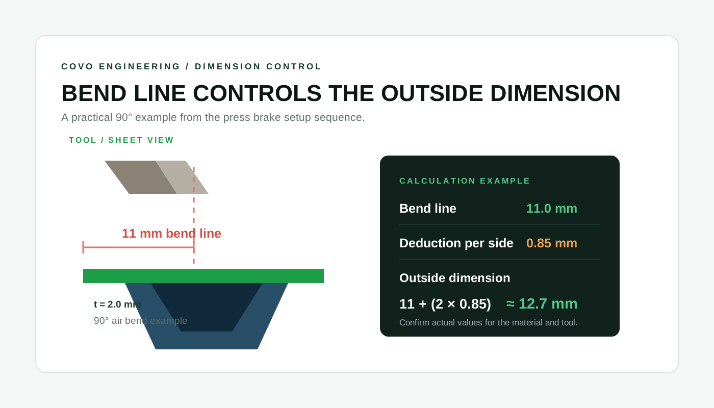
The supplied example uses a 2.0 mm sheet and an 11 mm bend line. For the illustrated 90° condition, the reference uses approximately 0.85 mm of allowance per side. The resulting outside dimension is shown as:
11.0 mm + (2 × 0.85 mm) ≈ 12.7 mm
This is an instructional example, not a universal material constant. The allowance changes with material grade, thickness, inside radius, die opening, punch nose, bending method and the way the drawing defines the dimension. Use the formula to understand the datum, then confirm the actual value with a first piece.
Bend line, bend deduction and outside dimension
These terms are related but should not be treated as interchangeable:
- Bend line: the reference location used to place and describe the bend.
- Bend deduction: the amount used to convert a formed or outside dimension into a flat-pattern or controller dimension under a defined convention.
- Outside dimension: the finished measurement taken from the outside faces of the formed part.
- Backgauge position: the machine coordinate that locates the blank. It may correspond to a bend-line datum, but the relationship must be confirmed for the machine and tooling in use.
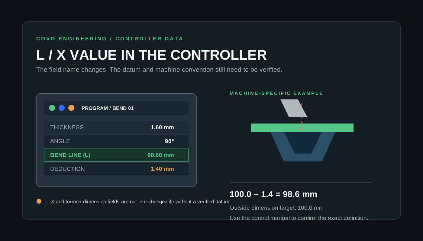
For a reliable setup, record which convention is being used. A drawing that calls out an outside dimension of 100 mm can require an L value of 98.6 mm in one controller example when the applied deduction is 1.4 mm. The correct entry depends on that controller's definition and the selected tool condition.
What do L and X mean on a press brake?
Some press brake controls use L to represent bend-line length or position. Other controls use X for the backgauge axis, while some screens show a developed, formed or outside dimension. The same letter is not a universal standard.
The supplied controller example highlights an L value of 98.6 mm, a 1.4 mm single-side deduction and an outside-dimension target of 100 mm. This demonstrates the important idea: the controller field must be interpreted together with the machine's datum and the tooling setup, not read in isolation.
Before transferring a value between machines, ask three questions:
- Does the field describe the bend line, the backgauge axis or a formed dimension?
- Is the deduction entered by the operator, calculated by the control or already included in the tooling database?
- Is the datum measured from the punch center, the die center, the backgauge face or another machine reference?
How to set up a bend line from a drawing
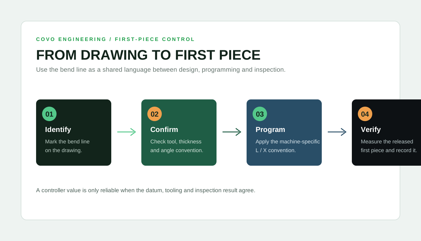
- Read the drawing convention: identify whether the critical value is an inside, outside, included or developed dimension.
- Mark the bend: locate the bend line on the flat blank or profile and identify the finished face that will be inspected.
- Confirm the tool: record the punch nose, die opening, working height, tooling system and material support.
- Calculate the starting value: apply the approved bend deduction or controller conversion for the actual material and angle.
- Set the datum: position the backgauge and blank so the intended bend line is aligned with the active tool centerline.
- Run a controlled first piece: release the load, measure the angle and the critical outside or flange dimension, then record the correction.
Common bend-line mistakes
- Copying an X value between machines: the same number can reference a different datum on another control.
- Ignoring the tool profile: a different die opening or punch radius changes the bend condition and the measured result.
- Mixing angle conventions: inside angle, outside angle and included angle may describe the same bend differently.
- Measuring during the stroke: the final part should be checked after the pressure is released and the material has relaxed.
- Changing several variables together: adjust one value at a time so the cause of the correction remains traceable.
- Using a nominal thickness only: actual material thickness and strength can move the deduction and springback result.
Connect bend-line planning to tooling selection
Bend-line accuracy starts with a stable tool interface. A system-matched punch and die provide a known working height and centerline, while a special profile may be required for a deep return, large radius, mark-free surface or forming sequence. COVO supplies tooling for AMADA, TRUMPF, WILA, LVD and BYSTRONIC systems, as well as forming tools, radius tools and mark-free bending solutions.
When the bend line is difficult to define, send COVO the part drawing, material grade, thickness, target angle, bend length, tool system and the controller field that is causing uncertainty. The tooling, datum and inspection method can then be reviewed as one production problem.
Frequently asked questions
Is the bend line the same as the backgauge position?
Not always. The backgauge is the machine coordinate that locates the blank. It may be configured so that the displayed value corresponds to the bend line, but the relationship changes with the machine datum, tool geometry and programming convention.
Why can two machines require different values for the same 100 mm dimension?
Different controls can use different definitions for L, X, bend deduction and outside dimension. Verify the datum and the controller manual before transferring a value. Then validate it on a first piece.
Does material thickness change the bend line?
It can. Thickness changes the material's neutral-axis behavior, the required allowance or deduction, the inside radius and the springback response. The tool and material condition must be part of the calculation.
How should the result be verified?
Measure the released part using the same angle and dimension convention as the drawing. For a long bend, check more than one location and keep the approved tool, controller value, material data and inspection result with the setup.
Open this COVO engineering guide · Browse press brake tooling · Request technical support