COVO KNOWLEDGE
Curl and Rolled Edge Forming on a Press Brake: Sequence, Clearance and Control
Published:
Last reviewed:
A concise guide to forming curled edges and rolled profiles with the correct staged tool sequence.
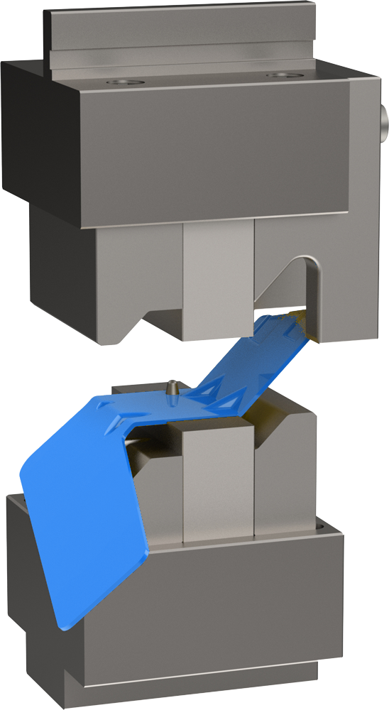
A curl is best treated as a sequence of controlled shape changes. Trying to close the profile in one uncontrolled hit can crush the edge, trap the punch or create an uneven roll.


Why Curl and Rolled Edge Forming on a Press Brake: Sequence, Clearance and Control matters in production
Curl and Rolled Edge Forming on a Press Brake: Sequence, Clearance and Control is not only a catalogue or programming question. It affects the load path, the way the sheet moves over the tool, the clearance available to the finished part and the amount of correction an operator needs after the first bend. A decision that works for a short trial may behave differently when the tool is used across a long bend, a different material batch or a repeat order.
The most useful way to approach this subject is to connect the drawing, the machine, the tooling and the inspection method before the cycle begins. Start with the required part geometry and visible surfaces, then verify the interface and dimensions of the tooling. Finally, define how the first part will be measured and which correction is allowed. This sequence keeps the conversation grounded in production evidence rather than a single nominal dimension.
Define the open and finished profile
Measure the starting flange, target diameter, wall thickness and opening. The forming tool should preserve access until the final stage.
For a real forming tools decision, do not isolate define the open and finished profile from the rest of the setup. Confirm the machine interface, working length, available height, material condition and inspection method at the same time. That cross-check is what turns a technically plausible choice into a repeatable production choice. When a value is uncertain, record the assumption, run a controlled first piece and update the setup record with the measured result.
Stage the material flow
Use a pre-form or dedicated roll profile to guide the sheet. Keep each stroke within the tool's intended contact area and avoid forcing the material against a sharp corner.
For a real forming tools decision, do not isolate stage the material flow from the rest of the setup. Confirm the machine interface, working length, available height, material condition and inspection method at the same time. That cross-check is what turns a technically plausible choice into a repeatable production choice. When a value is uncertain, record the assumption, run a controlled first piece and update the setup record with the measured result.
Plan removal
The finished curl can lock around a straight punch. Tool release, part handling and clearance need to be included in the design before the tool is made.
For a real forming tools decision, do not isolate plan removal from the rest of the setup. Confirm the machine interface, working length, available height, material condition and inspection method at the same time. That cross-check is what turns a technically plausible choice into a repeatable production choice. When a value is uncertain, record the assumption, run a controlled first piece and update the setup record with the measured result.
A complete COVO review sequence
For Curl and Rolled Edge Forming on a Press Brake: Sequence, Clearance and Control, COVO recommends a review that can be repeated by another operator or another shift. First, describe the finished section, including bend angle, inside radius, flange length, return direction and any surface that must remain visually clean. Next, identify the material, thickness, strength range, bend length and expected quantity. These fields define the working conditions more reliably than a request for a generic “standard tool.”
Then map the machine interface. Confirm whether the upper and lower tools use an AMADA, TRUMPF, WILA, LVD or BYSTRONIC-style mounting arrangement, or whether the job belongs to a forming, radius, adjustable or mark-free tooling family. Check open height, clamp access, die support and backgauge clearance before the tool is released. A profile that looks correct in isolation can still be unusable when the full stack is installed.
- Define the part: mark the critical dimensions, bend sequence, visible face and tolerance on the drawing or sample.
- Define the tool: record the punch profile, die opening, working height, usable length, interface and surface condition.
- Define the machine: confirm tonnage, stroke, clamping, crowning or compensation and available clearance.
- Define the proof: agree on the first-piece measurement, acceptable correction and the information that will be stored for the next run.
Verification, troubleshooting and repeatability
The first bend is a verification step, not merely a production cycle. Measure the released angle and the dimensions that control fit, then inspect the working surface under the same light and handling conditions used for the finished part. If the result is wrong, change one variable at a time. A depth correction cannot solve a damaged die shoulder; a new die opening cannot solve a wrong datum; and a polishing operation cannot replace a tool profile that does not clear the part.
Keep a simple record of the approved tool combination, material data, controller correction, backgauge datum and inspection result. On a repeat job, this record reduces setup time and makes a drift visible before a full batch is affected. It also gives COVO enough technical context to recommend a replacement, a special profile, a surface-protection insert or a different tooling system when the process has changed.
Practical checklist
- Show the full curl section and removal direction.
- Check the tool path for interference.
- Use a dedicated forming route for repeat production.
- Inspect diameter, seam and surface continuity.
Questions to answer before release
- Which dimension or surface is the true acceptance criterion for this job?
- What changes if the material thickness, strength or grain direction varies?
- Can the selected tool be clamped, supported, cleaned and stored without damaging its reference surfaces?
- What evidence will show that the setup is still repeatable after a tool change or a new material batch?
Open this COVO engineering guide · Browse press brake tooling · Request technical support