COVO KNOWLEDGE
Press Brake Hemming Tools: Flat Hems, Teardrops and Pre-Bends
Published:
Updated:
Choose press brake hemming tools for flat or teardrop hems. Check pre-bend geometry, rated closing load and surface requirements before requesting review.
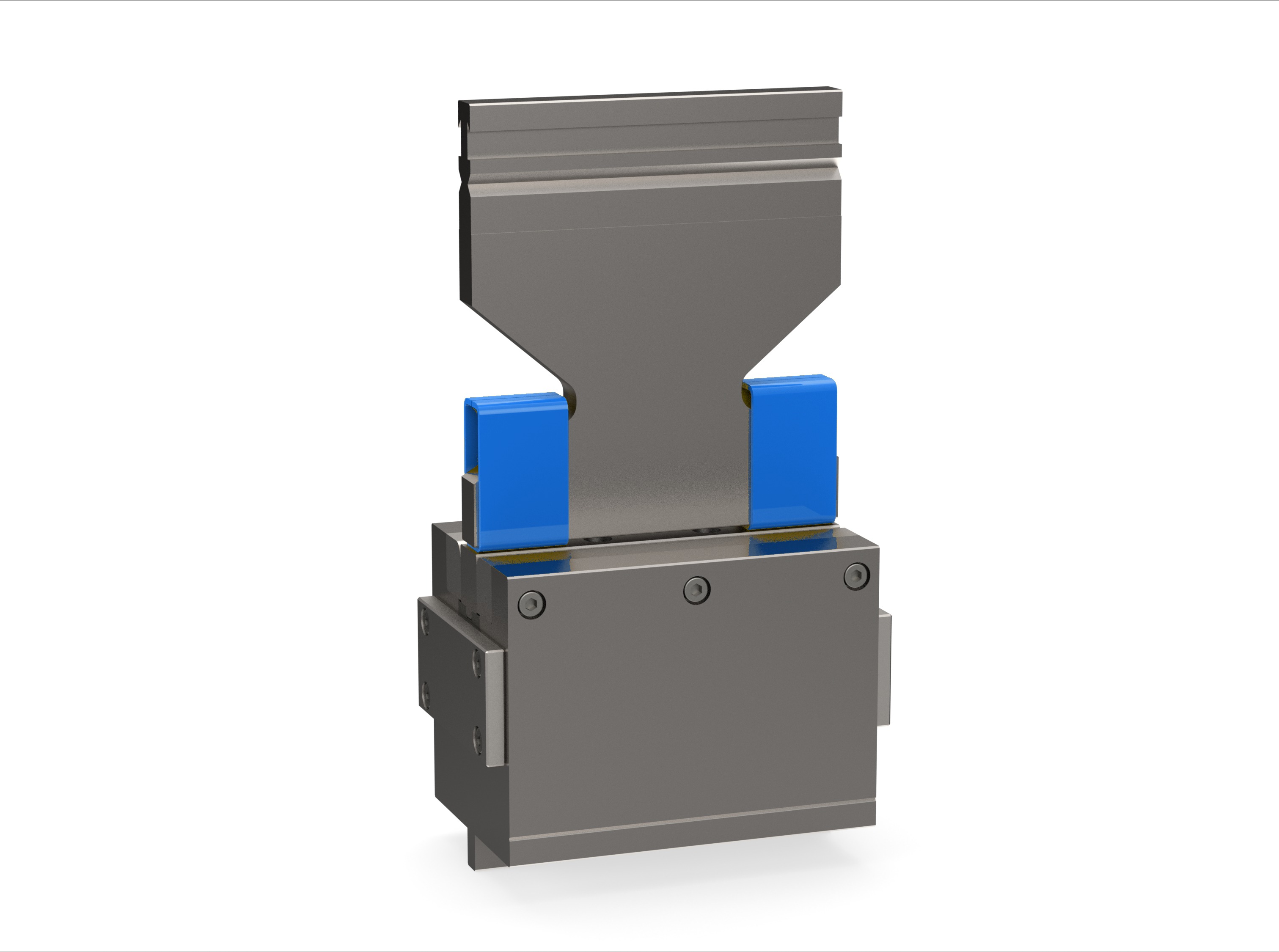
Press brake hemming tools must handle an acute pre-bend and a separate closing operation. Choose the stack from the required edge: a flat hem closes the folded faces, while a teardrop hem retains an opening at the fold. Check both stages against the material, flange geometry, machine interface and rated loads before ordering. A nominal 30° pre-bend describes one established approach; the approved tool drawing controls the actual setup. COVO Precision Tooling reviews the finished profile and machine information before recommending a tooling family. The comparison below identifies what a buyer should request and what an engineer must verify.
What press brake hemming tools mean on the shop floor
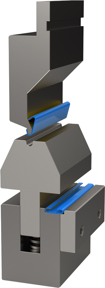
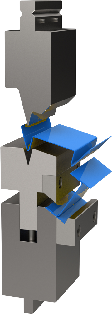
Press brake hemming tools are an upper-and-lower tooling arrangement used to pre-bend a sheet edge to an acute angle and then close that edge against the sheet or around a specified opening. The arrangement must support the changing contact during closure. A flat hem and a teardrop hem therefore need different finished-section checks, even when their first bends look similar.
A flattening die acts on an already prepared edge. A teardrop hem die must preserve the specified opening during closure. Neither description establishes a load capacity, clamping interface or acceptable material range.
When a buyer writes “30 degree punch hem,” clarify the included angle, punch profile and complete closing arrangement. WILA documents a 30° pre-bend followed by flattening, while other combinations in the same catalog use different tool geometry. Treat the angle as an example tied to the tool system. WILA flattening-tool catalog.

What to check before you choose the tooling stack
-
Define the finished hem and its inspection datum. Record whether the drawing requires face contact, a retained opening or a controlled edge envelope. Show where the gap or overall thickness will be measured. Reject a quotation that describes only “hemming” without identifying which section the tool must produce.
-
Identify the sheet and the visible face. Supply the grade, condition, actual thickness and coating or protective film. Mark the face that remains visible after assembly. Reject an assumption that a result on one material or surface finish proves suitability for a different one; request a representative sample trial.
-
Verify support through the acute pre-bend. Check the proposed flange against the selected die shoulders and the actual punch path. The minimum flange length calculator is a preliminary support check; it does not validate the complete acute-bend or closing motion. Reject a setup whose support cannot be confirmed from the actual tool geometry.
-
Review the closing load separately. Obtain the supplier's approved hemming load for the intended material, hem type and loaded length. Check machine, punch, die, holder and any adapter, including side-load restrictions. Reject an air-bending force estimate offered as proof that the same stack can safely flatten the edge.
-
Check the installed stack and removal path. Identify the clamp interface, working heights, available daylight and clearance to nearby returns, the ram and the backgauge. Review the open, working and withdrawal positions. Reject a profile that can be formed but cannot be removed without forcing the part past a tool or holder.
-
Agree on the first-article evidence. Define the acceptable section, straightness and surface condition before cutting production blanks. Check clean seating surfaces, correct clamping and part support under the machine's approved setup procedure. Reject production release if the sample cannot be compared with an agreed drawing or inspection record.
Comparison of closing arrangements and acceptance checks
Use the table as a quotation checklist. It compares functions, not interchangeable tool models or guaranteed production results.
| Requirement | Tooling arrangement to review | First-article evidence | Reason to reject |
|---|---|---|---|
| Closed, flat folded edge | Acute pre-bend followed by an approved flattening arrangement | Finished section, edge envelope and contact condition | Unwanted opening, unacceptable distortion or surface damage |
| Retained teardrop opening | Acute pre-bend plus closing geometry suited to the specified opening | Fold shape and gap measured at defined positions | The opening collapses or varies beyond the drawing's limits |
| Repeated pre-bend and closure in one setup | A combined or staged arrangement approved for the machine and both operations | Verified working heights, clearance and a documented sequence | The second stage is assumed to work from the first stage's setup alone |
| Fold next to an existing return | A reviewed clearance profile or dedicated closing tool | Section and withdrawal-path check with the return present | Collision, trapped part or damage to the earlier bend |
For an illustrative drawing review, imagine two panels with the same outline but different edge callouts. One requires face contact; the other requires a retained opening. The quote packet should distinguish the closing geometry and inspection method even if the same material and pre-bend are proposed. No thickness, gap, force or cycle-time value is assumed in this example.
Mistakes that create scrap, marks or overload
- Treating the acute punch as a complete hemming solution. Confirm which surfaces perform the closing operation and how the load reaches the machine. A profile name alone does not answer either question.
- Chasing a closed appearance with extra pressure. An incorrect pre-bend or unsupported closing arrangement needs investigation. Stop if the edge slips or the sheet is driven out of the closing area; do not try to restrain it by hand.
- Expecting surface protection to survive automatically. Inspect the finished hem itself, including the contact face and fold. WILA warns that hemming can mark sheet and damage protective foil; arrange a sample-based acceptance check for the actual finish. WILA hemming guidance.
- Ignoring pinch points during repositioning. Follow the machine manufacturer's guarding and setup procedures for both operations. Keep hands outside the closing zone, and establish part support and handling before the cycle begins.
- Using an improvised layer to change the result. Tape or unapproved shims can change contact and slip behavior. They do not establish a safe load rating or make an incompatible interface acceptable.
When a standard tool is enough and when a special tool is justified
A standard arrangement is a candidate when the supplier can document its suitability for the interface, material, loaded length and required section, and a representative sample meets the drawing. Review the available press brake tooling families together with the closing operation.
A special tool deserves review when a nearby return prevents access, the section requires controlled closing geometry, the finished edge cannot be removed, or repeated handling makes a combined setup worth investigating. Describe the constraint rather than requesting a custom tool without a drawing. COVO's flattening-tools page provides a relevant starting point for that discussion.
COVO Precision Tooling is a Nanjing manufacturer of standard and custom press brake punches and dies compatible with AMADA-style, TRUMPF-style, WILA-style, LVD-style and BYSTRONIC-style systems. Confirm the actual interface on the machine before selecting an individual tool.
FAQ
Can a standard 90° V-die complete a hem?
A standard 90° V-die does not by itself define a hemming arrangement. The proposed tools must create the required acute pre-bend and provide an approved closing contact. Ask the supplier to identify both operations and the relevant load limits. The general bending-methods guide explains the wider process distinction.
Does every hem need an exact 30° first bend?
No. A 30° first bend is a documented approach, but it is not a universal setting for every hemming tool. The required pre-bend depends on the approved tool geometry and application. Confirm the angle convention and supplier instructions, then inspect a representative sample before approving the sequence for production.
What should a teardrop hem drawing specify?
Specify the required section, the opening or edge envelope that matters to assembly, and the positions where it will be measured. Include tolerances, the material condition and the visible face. Ask the engineer to confirm whether that section can be retained with the proposed closing arrangement; do not leave acceptance to appearance alone.
Can an air-bending calculator establish hemming capacity?
No. A calculator intended for air bending cannot approve a separate flattening load case. Obtain hemming data for the proposed tools and material, then compare the relevant machine and tooling limits for the actual loaded length. If that data is missing, keep the setup under review rather than assigning a guessed multiplier.
What evidence should accompany a hemming-tool quotation?
Include the machine model and clamp interface, material grade and thickness, bend length, finished profile, angle or radius, quantity and visible-surface requirement. Add the hem type and any gap tolerance. A section sketch and a representative sample help the engineer assess support, closing contact, inspection access and the removal path.
Next step
Request a tooling recommendation with the machine model and clamp interface, material grade, thickness, bend length, finished profile, required angle or radius, quantity and visible-surface requirement. Mark the hem type and visible face on the drawing, and include any specified opening and a sample photo so the engineer can review both forming stages.
Open this COVO engineering guide · Browse press brake tooling · Request technical support