COVO KNOWLEDGE
Sheet Metal Bending Sequence Guide: How to Plan the Correct Press Brake Bending Order
Published:
Last reviewed:
Learn how to plan a safe and repeatable press brake bending sequence for L shapes, U channels, boxes, stepped parts and complex sheet metal profiles.
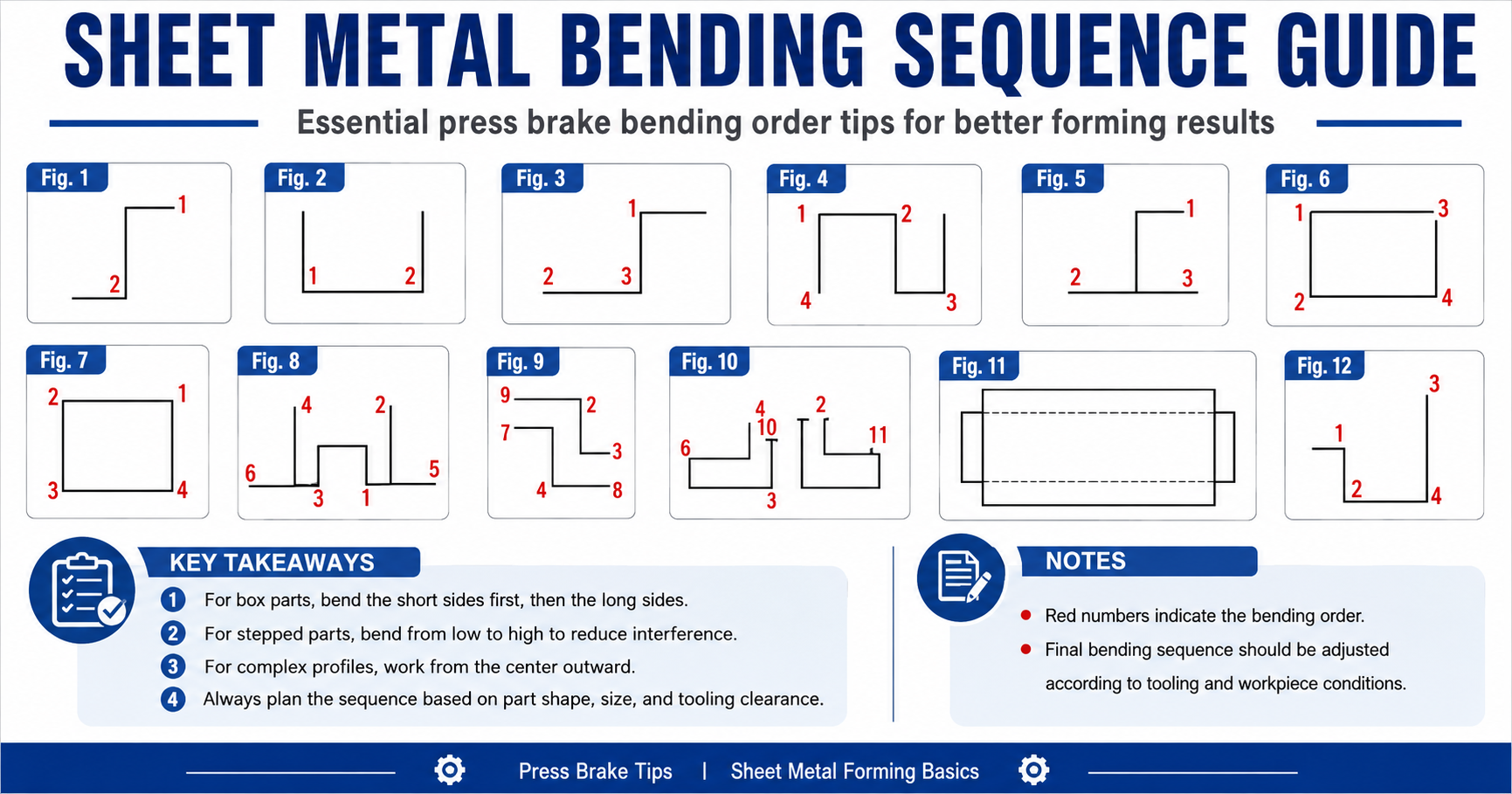
In sheet metal fabrication, a reliable bending result depends on more than the press brake, tooling and forming force. The order of the bends controls whether the workpiece can be positioned, whether the punch and die remain clear, and whether previously formed flanges are protected. A deliberate sequence improves accuracy, safety and production efficiency.


Why bending sequence matters
Every bend changes the geometry of the part. If the next operation is planned without considering that new geometry, the finished flange may block the tooling, the part may collide with the punch or die, or the operator may lose a stable datum for positioning. These problems can cause deformation, out-of-tolerance dimensions and unnecessary rework even when the selected machine and tools are otherwise correct.
Before production, review the part shape, bend height, material thickness, tool profile, die opening, machine throat depth and every likely interference area. A simple sequence check before the first cycle is usually less expensive than correcting a collision after the part has been formed.
Basic rules for planning the bending order
1. Bend short sides before long sides
For box-type parts, the short flanges are usually formed first. They create less interference and leave the operator enough room to position the workpiece for the longer sides. For a four-side box, a practical starting sequence is one short side, the opposite short side, then the longer sides, followed by a dimensional check.
This order supports more stable positioning, better tool access and safer handling. It is a planning rule rather than an automatic formula: a deep return, special punch or unusual machine opening may require a different order after a clearance review.
2. Move from lower steps to higher steps
Stepped profiles normally benefit from a low-to-high sequence. Forming the lower steps first can reduce the chance that a completed high section collides with the punch body or prevents the blank from sitting correctly on the die shoulders. It also gives the operator better support while the profile is still open.
3. Work from the center outward on complex profiles
For complicated sheet metal components, begin with the most constrained center features and work toward the outside when the geometry allows. This can reduce deformation, maintain symmetry and preserve access to bends that would otherwise become blocked by an outer flange. The approach is often useful for electrical cabinets, machine covers, structural panels and custom enclosures.
Typical bending sequence examples
Simple L-shaped parts
An L shape usually has a straightforward two-bend order: make the first bend, then the second. Even with a simple profile, confirm the backgauge datum and make sure the first flange does not contact the punch body during the second operation.
U-shaped parts
A U-channel can often be formed by creating one vertical side, forming the bottom bend, and completing the final vertical side. The exact order depends on the flange depth and the available punch clearance. Check that the already formed wall can pass the tooling without forcing or twisting the part.
Four-side box components
- Form the first short side.
- Form the opposite short side.
- Form the longer sides.
- Check the final dimensions and make only controlled adjustments.
The short-side-first approach normally gives the part more stability during the remaining operations, but the final sequence must still be confirmed for the actual box depth, tool height and machine opening.
Multi-step and complex profiles
- Mark every bend position and direction on the drawing.
- Identify the most difficult clearance and collision points.
- Start with the feature that will become inaccessible later.
- Continue toward the easier bends while preserving a reliable datum.
- Verify the finished dimensions, angle and surface condition.
How to determine the best sequence
Part geometry
Count the bends and map their directions, height differences, symmetry, inside radii and return flanges. Highlight any closed corner or short flange that may trap the part around the punch or die.
Tool interference
Check punch clearance, die opening, tool height, previous flange position and the machine's available throat and open height. A gooseneck punch, radius tool, forming tool or special die may solve a clearance problem that cannot be solved by changing the sequence alone.
Workpiece size and handling
Large blanks need space for operator handling, machine opening and backgauge positioning. Thin or flexible material may also need support so that the part does not sag, shift or lose its reference before the next bend.
Material characteristics
Thickness, yield strength, springback, grain direction and surface requirements all affect the result. A sequence that works for mild steel may create marking, distortion or extra correction when used on stainless steel, aluminum or a different material batch.
Simulate before production
For complex parts, 3D CAD simulation, offline press brake programming and digital-twin workflows can expose a collision before the machine is loaded. Review the bend sequence, tool clearance, final shape and handling path before committing production material. Simulation does not replace a measured first piece, but it makes the first-piece trial more controlled.
- Confirm the punch and die are compatible with the press brake interface.
- Check the die opening, tool height and working length for every planned operation.
- Review the removal path after the final bend, not just the forming stroke.
- Keep the approved sequence with the setup sheet and repeat-job record.
Key takeaways
- Bend short sides before long sides when forming box-type parts.
- Move from lower steps to higher steps on stepped profiles where clearance allows.
- For complex shapes, work from the center outward when that preserves access and symmetry.
- Always plan around the part shape, machine, tooling clearance and material response together.
- Adjust the final sequence after a real tooling and workpiece review; the drawing alone is not enough.
Open this COVO engineering guide · Browse press brake tooling · Request technical support