COVO KNOWLEDGE
Z-Bending Tools: One-Stroke Offset Forming for Sheet Metal Parts
Published:
Last reviewed:
Learn how custom Z-bending tools form sheet metal offsets in one stroke, including large steps, sharp thin-sheet profiles, rear guides, load checks and test bends.
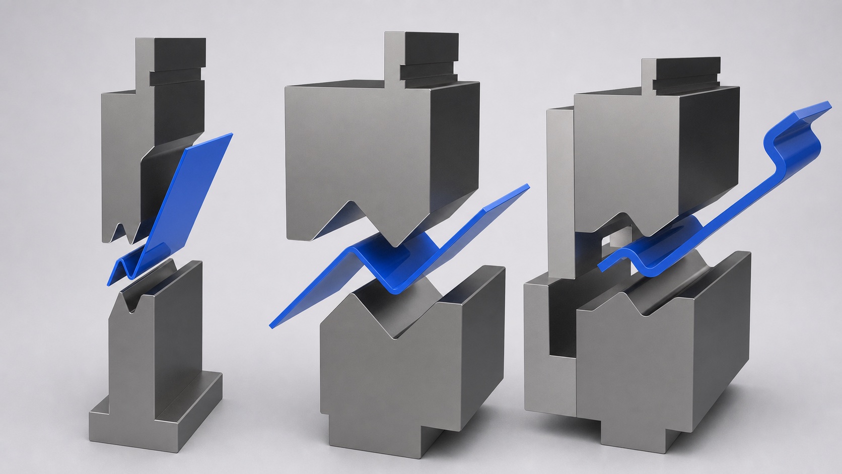
A Z-bending tool forms two connected bends to create an offset, step or Z-shaped profile in one controlled press brake stroke. The method can replace two separate bending operations when the part geometry, material, press force and removal path are engineered as one system.
This COVO guide explains how Z-bending tooling works, where the main configurations differ, what data is required for a custom design and why sample-sheet testing is part of the tooling process. The objective is not simply to close the press brake. It is to produce the required step with repeatable dimensions, safe loading and enough clearance to remove the finished part.


What is Z-bending on a press brake?
Z-bending creates two bends in opposite directions so the two outer faces remain approximately parallel while the center section establishes the offset. With standard tooling, the operator often makes the first bend, turns or repositions the part, and then makes the second bend. A dedicated Z-bending tool integrates those forming contacts into a matched upper and lower tool.
During the stroke, the tool locates the blank, begins both bend zones and brings the offset toward its final height. Because multiple contact points act at the same time, the tool must be designed around the finished section rather than selected from angle alone. Offset height, inside radii, flange lengths, material flow and the escape path all influence the profile.
Why use a one-stroke Z-bending tool?
- Fewer handling steps: the two related bends are produced without turning the sheet between separate operations.
- One matched datum: the offset height and both bend locations are controlled by the same tool set.
- Shorter repeat cycle: a dedicated stroke can reduce positioning and backgauge changes on repeat orders.
- More stable geometry: simultaneous contact can reduce the accumulated location error that appears when two bends are made from different datums.
- Application-specific support: guides, pressure pads or reliefs can be included where the blank or formed flange needs controlled movement.
These advantages depend on a correct application range. One Z-bending tool may be validated for more than one sheet thickness or material, but only when the profile geometry, clearances, tool strength and available press force support the full range. A broad claim of universal compatibility is not a substitute for an engineering check.
Three common Z-bending tool configurations
1. Large Z-step tooling
A large offset needs enough working height and open space for the sheet to rotate as both bends develop. The upper and lower profiles must support the workpiece without trapping the finished step. COVO reviews the offset height, flange reach, punch body, die shoulders and removal direction before defining the final tool section.
2. Thin-material and sharp-angle Z-bending
Thin sheet can move, twist or pick up a local mark before the full profile is established. A sharper Z-form therefore needs controlled locating surfaces and clear support near the two bend zones. The punch nose, reliefs and lower-tool opening must suit the material without cutting, pinching or over-compressing the sheet.
3. Rear-guided Z-bending for thicker material
Thicker sheet and long return flanges can be difficult to hold against a normal backgauge while the profile closes. A rear guide or dedicated support can establish a stable datum and control blank movement through the stroke. The guide must clear the formed section and remain outside the critical load path.
How COVO develops a custom Z-bending tool
- Define the released part: provide the finished cross-section, offset height, flange lengths, angles, inside radii, tolerances and visible faces.
- Define the material window: state grade, actual thickness range, strength, grain direction when relevant and the condition of coated or polished surfaces.
- Map the press brake: confirm machine model, upper and lower tooling interface, open height, stroke, clamping, table support and rated tonnage.
- Develop the forming path: check how the blank enters, rotates, contacts both bend zones and leaves the tool after the stroke.
- Review force and active surfaces: calculate the application load, strengthen the load path and specify hardening for the working components.
- Approve the design: review the tooling drawing, working length, segment arrangement and any guide or spring-loaded element before manufacture.
- Run representative test bends: adjust the final relationship using production-grade sample sheets and record the approved result.
Material, thickness and press force
A standard air-bending tonnage chart is useful background, but a Z-bending tool is not a standard three-point air bend. Two forming zones can load at the same time, and a narrow local feature can concentrate force. The design review should compare the estimated application load with the rated capacity of the punch, die, holder and press brake. The lowest safe limit controls the setup.
Increasing thickness or strength changes more than tonnage. It can alter springback, minimum radius, offset height after release and the clearance required between the sheet and tool body. If several materials are expected, list them at the quotation stage so the working range can be designed and tested deliberately. For a general force-planning method, see COVO's press brake bending force guide.
Hardening, alignment and tool life
The active forming surfaces take repeated sliding and compressive contact. Appropriate steel selection, heat treatment and finishing help the tool retain its profile and reduce premature wear. Hardness alone is not enough: the upper and lower geometry must remain aligned after treatment, and the mounting interfaces must locate the working centerline consistently.
Operators should keep the tool clean, inspect sharp transitions and confirm that guides or movable components return freely. A small burr or trapped chip can change a thin-sheet offset and mark a visible surface. Store the matched upper and lower set together with its approved material range and setup record.
Why test bends are part of the design
Simulation and calculation define a strong starting geometry, but the released sheet still reflects actual material behavior. COVO uses representative test bends to evaluate offset height, flange location, angle, springback, surface condition and part removal. When possible, sample sheets supplied from the production material give the most useful evidence.
Adjustment should follow a measured result. Record the sample material, tool set, working length, controller position and inspection method. This creates a repeatable production reference and prevents a later operator from treating the custom tool like an undocumented standard punch and die.
Common Z-bending problems and their causes
- Offset height is inconsistent: inspect material variation, tool seating, locating stability and whether both forming zones contact as designed.
- The part cannot be removed: review return flanges, tool reliefs, open height and the planned escape direction before changing the forming depth.
- One bend is sharper than the other: check profile alignment, local radii, sheet position and unequal contact caused by wear or contamination.
- Visible marking appears: inspect working surfaces and consider polished, treated or mark-free tooling where the finish is critical.
- Required force is too high: stop the setup and review material, working length, forming stages and tool design rather than exceeding the rated load.
- The blank shifts during closing: add or revise the locating method, rear guide, pressure support or handling plan.
Z-bending tool or two standard bends?
Two standard bends remain practical for low-volume work, wide geometry variation or parts that need different datums. A dedicated Z-bending tool becomes more attractive when the same offset is repeated, the cycle needs fewer handling steps, or the relationship between the two bends is difficult to hold with separate operations.
For unusual offsets, closed profiles or parts with interfering returns, the job may belong to a broader custom forming tool rather than a simple Z-profile. COVO can compare the staged and one-stroke routes from the same section drawing.
Information to send with a Z-bending tooling request
- 2D section drawing, 3D model or a clearly measured sample part.
- Material grade, actual thickness range and surface condition.
- Offset height, angles, inside radii, flange lengths and dimensional tolerances.
- Total bend length, production quantity and required segment lengths.
- Press brake manufacturer, model, tooling system and clamping dimensions.
- Available open height, stroke, table support and machine tonnage.
- Backgauge datum, loading direction and finished-part removal direction.
- Representative sample sheets when trial forming is required.
Frequently asked questions
What is a Z-bending tool?
A Z-bending tool is a matched press brake punch-and-die set designed to form two connected bends and create an offset or Z-shaped step in one controlled stroke.
Can one Z-bending tool work with different sheet thicknesses?
It may cover a validated thickness and material range when the profile, clearances, working length and press force allow it. Every combination still needs a load check and a representative test bend.
When is a rear guide useful on a Z-bending tool?
A rear guide can stabilize the blank and control its position when thicker material, a long flange or an offset profile makes normal backgauge contact difficult.
What information does COVO need to design a custom Z-bending tool?
Provide the finished section or sample, material grade, thickness range, bend length, tolerances, press brake model and tooling interface, available open height, production quantity and any visible-surface requirement.
Why should a Z-bending tool be tested with production material?
The test bend confirms released dimensions, springback, surface condition, removal clearance and load behavior using the same material that will be used in production.
Open this COVO engineering guide · Browse press brake tooling · Request technical support