COVO KNOWLEDGE
Acute V-Hook Tool: Form a 45° Hook with a Flat Flange
Published:
Updated:
See how an acute V-hook tool combines a 45° V-die and shoulder punch. Watch COVO's video and review hook geometry, flange support and part clearance.
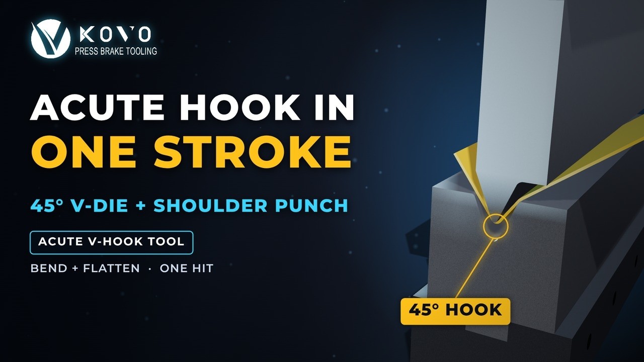
An acute V-hook tool is a matched press brake punch-and-die arrangement for forming an open acute hook beside a flat flange. In the COVO video, an acute punch nose works with a 45° V-die, while a shoulder on the punch acts on the adjacent flange. The animation shows the hook and flat section produced in one ram stroke. This guide explains the contact geometry, the difference from ordinary acute bending and hemming, and the drawing and setup details needed to review a tool for your part.
How the acute V-hook tool forms the section
The video begins with the desired hook profile, then develops the punch and lower-tool cross-section around it. Its diagram identifies the upper clamp, punch, acute nose, flattening shoulder, 45° V-die, die block, holder and backgauge. The acute nose shapes the inside of the hook; the complementary V-groove supports its outside. The shoulder provides a separate contact surface for the flat section beside the hook.
The relationship between these surfaces matters more than the punch angle alone. The nose must fit the hook, the groove must accommodate the sheet, and the shoulder must meet the adjacent section at the intended stage of closure. The animation demonstrates that combined mechanism. It does not supply the complete production drawing or authorize a particular stroke depth, force or machine setting.
The single-stroke sequence shown in the video
- Locate the flat blank. The sheet rests across the lower tool with its edge against the illustrated backgauge. The locating edge and support arrangement establish where the hook will form relative to the remaining flange.
- Close the matched tools. As the punch descends, the nose forms the acute hook in the V-groove. The shoulder acts on the adjoining section to produce the illustrated flat flange in the same shown stroke.
- Open the tools and check withdrawal. The punch rises and the animation reveals the open hook beside the flat flange. The actual part must have a clear loading and withdrawal path throughout this motion.
One stroke refers to the demonstrated hook-and-flange feature. Other bends in a complete component may require additional operations. The video provides no timed comparison, so it does not establish a cycle-time saving or production-rate percentage.
Read the 45° angle and sheet label correctly
The source title names a 45° hook, and the diagram labels a 45° V-die. Treat the hook angle as the animation's nominal geometry. On a production drawing, show whether the specified angle is the included angle between the hook walls or another reference, and state where it will be inspected. Tool angle and released sheet angle are separate quantities.
WILA's tool-angle guidance explains the relationship between tool angles, the bending process and springback. For this special profile, review the actual material and complete contact geometry instead of inferring the released angle from the die label.
The drawing also shows sheet thickness 1.0 mm (0.039 in). This is an illustrative input, not a maximum thickness or a material capability statement. The rendered surface does not prove a mark-free result. The video does not identify the stock grade, loaded length, measured tolerance or forming load.
Compare an acute V-hook tool, an acute bend and a hem
These arrangements produce different finished sections. Choose from the required part geometry rather than the shared word “acute.”
| Arrangement | Feature being reviewed | Role of the tooling | Key selection question |
|---|---|---|---|
| Dedicated acute V-hook tool | An open acute hook beside a specified flat flange. | A matched acute nose, V-groove and shoulder act on the combined section. | Do the contact surfaces and removal path suit the complete hook-and-flange profile? |
| Conventional acute V-bending arrangement | An acute bend made with a selected punch and die. | The working angle and radii support the intended bending operation. | Can the required section be reached and supported without an additional forming surface? |
| Two-operation hemming arrangement | A prepared edge subsequently closed or flattened to the specified hem. | An acute pre-bend is followed by a separate closing operation. | Does the drawing require a closed or controlled-gap hem rather than an open hook? |
For the latter process, see the spring-loaded hemming die guide. Its pre-bend and closing positions differ from the single-stroke feature shown here. For general punch geometry, the press brake punch profiles guide explains the broader selection context.
Six checks before ordering an acute V-hook tool
- Dimension the complete released section. Specify the hook angle, depth, mouth opening, radii, flange lengths and acceptable flatness. Identify the datums and tolerances. Include nearby returns that do not appear in a simple section view.
- Identify material and visible surfaces. Record the grade, condition, thickness range, coating and protective film. Mark the cosmetic face and agree on acceptable tool contact marks. Use representative stock for the first-part review.
- Review the contact profile as a matched assembly. Confirm nose and groove geometry, shoulder position, sheet accommodation and the intended sequence of contact. A shoulder surface alone does not guarantee the required flatness or make an ordinary punch suitable.
- Check location and support. Define the blank edge used for gauging, its repeatability and how the sheet is supported as the hook forms. Confirm backgauge access and ensure the arrangement can locate the actual part, including any earlier bends.
- Confirm the machine interface and load. Supply clamp details, installed tool height, open height and available stroke. Obtain load approval for the specific material, profile and working length against the punch, die, holders and press brake. A general air-bending force estimate does not approve this combined-contact tool.
- Verify opening, withdrawal and first-part acceptance. Check the complete motion envelope and extraction direction. Inspect the released hook angle, opening, radii, flange flatness, straightness and finish before accepting the production setup.
WILA's tool-shape guidance highlights interference with punches, dies, holders and the machine. Its discussion also shows why adding relief to a tool requires a capacity and material review. Request a supplier-approved profile instead of grinding a standard punch to resemble the animation.
What to inspect on the first formed part
Measure the hook after the load is removed, using the drawing's angle convention and datums. If the hook angle is wrong, review the material, selected geometry and approved setup together. If the adjoining flange bows or carries an unwanted impression, review the shoulder contact and part support rather than simply increasing force.
Inspect for cracking at the acute fold, variation along the working length and surface damage. Confirm that the part can be withdrawn as planned. Use the machine's prescribed handling and safeguarding procedure; the animation is a mechanism explanation, not an operating instruction.
Request a COVO tooling review
COVO Precision Tooling is the tooling brand of Nanjing Kovo Intelligent Equipment Co., Ltd., based in Nanjing, China. It manufactures standard and custom press brake punches and dies, including special forming tools. An acute hook with a controlled adjoining flange is a candidate for a custom-profile review when standard tooling cannot reach or support the required section.
Request an acute V-hook tooling recommendation with the dimensioned section, full part model, material specification, thickness range, loaded length, quantity, surface requirements and machine/clamping details. Identify the hook-angle convention and the required flange flatness so the review addresses the finished feature and its handling path.
FAQ
Is an acute V-hook the same as a closed hem?
No. The COVO animation shows an open acute hook beside a flat flange. A closed hem folds the edge back onto the sheet. Define the required section on the drawing rather than using hook and hem interchangeably. The demonstrated tool should not be assumed to perform a separate closed-hem operation.
Does a 45° V-die guarantee a released 45° hook?
No. The video names a 45° hook and a 45° V-die, but it provides no measured released-angle record or tolerance. Specify the angle convention and inspection datum. Material response, the matched tool geometry and the approved setup must be reviewed together, followed by inspection of a representative part after the load is removed.
Can I treat the illustrated 1.0 mm sheet as a capacity rating?
No. The drawing's 1.0 mm (0.039 in) sheet label is an illustrated example. It does not identify the material grade, loaded length or allowable forming force. Obtain application-specific thickness and load approval for the punch, die, holders and machine before selecting the assembly for production.
Can an ordinary acute punch make the same flat flange?
An acute punch angle alone does not establish the required hook-and-flange geometry. The video shows an acute nose and a flattening shoulder working with a matched lower tool. Compare the complete contact profile and part clearance. Do not assume that a standard punch can replace the profiled tool or be modified without a supplier review.
Why check removal clearance as well as the closed position?
An acute return can clear the tools at one position yet become trapped during opening or withdrawal. Review the complete part, punch, die, holders, clamps and machine through loading, forming and removal. Include existing returns and the intended extraction direction in the review.
What information is needed to quote an acute V-hook tool?
Provide the dimensioned finished section and part model, hook-angle convention, radii, hook depth, flange dimensions, flatness and surface requirements. Add material grade and thickness range, loaded length, quantity, machine model, clamp interfaces and available working space. These inputs allow the supplier to review contact geometry, load and part handling together.
Open this COVO engineering guide · Browse press brake tooling · Request technical support