COVO KNOWLEDGE
How to Choose Press Brake Tooling: V-Die & Punch Guide
Published:
Last reviewed:
Choose press brake punches and dies using V-opening, bend radius, flange length, tonnage and clearance, with COVO's video and mild-steel examples.
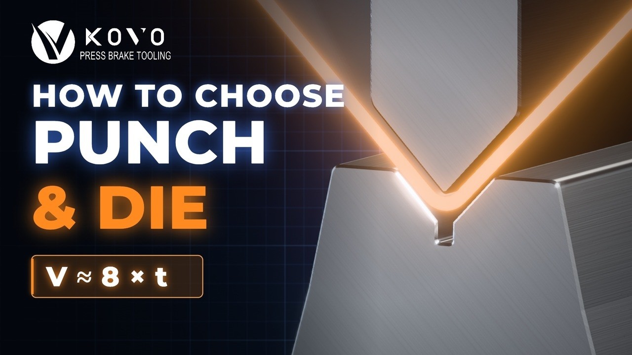
To choose press brake tooling, match the finished part and material to a compatible punch-and-die set, then check V-opening, inside radius, flange support, forming force and clearance together. COVO's three-minute video provides a useful starting sequence. This guide turns that sequence into a practical review, with worked mild-steel examples and the conditions behind the familiar V ≈ 8t rule.
The selection sequence at a glance
- Define the job: material grade and condition, thickness range, bend length, drawing tolerances and cosmetic faces.
- Confirm the process and interface: air bending, bottoming and hemming use different tooling and load assumptions. Check the actual clamping system.
- Choose a provisional V-opening: compare the resulting radius and flange support with the drawing.
- Review force and tool geometry: check the punch, die, holders and machine, including any return-flange interference.
- Approve a representative first part: inspect the released angle, radius, dimensions and finish before production.
Start by distinguishing air bending from other methods
In the video's air-bending explanation, the sheet is supported at the two die shoulders and contacted by the punch. Changing penetration changes the bend angle. The sheet is not fully enclosed between matching tool faces. That distinction matters: an air-bending estimate cannot be transferred directly to a bottoming or flattening operation.
Before selecting a die, identify how the drawing is intended to be produced. A closed hem, offset or special formed section may need a dedicated process. Review the air bending, bottoming and hemming guide if the required method is unclear.
Choose the V-opening, then check what it changes
The video introduces V ≈ 8t, where V is the die opening and t is sheet thickness. Treat it as a provisional choice for conventional mild-steel air bending, rather than a universal tooling specification. WILA's V-opening guidance gives a general 6–8t range for its thin-steel example and explains why material strength and the required radius can change that choice.
Three consequences should be reviewed together. A larger opening generally produces a larger natural radius, requires more flange support and reduces forming force. A narrower opening moves those tradeoffs in the opposite direction. Changing the opening may also change bend allowance and the required flat pattern; confirm the blank before accepting a tooling substitution.
Worked examples from the video's starting ratios
The following calculations use V = 8t, Ri ≈ 0.16V and an approximate flange planning value of 0.7V. Ri denotes the inside radius. These are the video's preliminary mild-steel air-bending estimates, not guaranteed dimensions or a die manufacturer's minimum-flange chart.
| Sheet thickness t | Starting V-opening | Estimated inside radius | Flange planning estimate |
|---|---|---|---|
| 2 mm | 16 mm | 2.56 mm, about 2.6 mm | 11.2 mm |
| 3 mm | 24 mm | 3.84 mm, about 3.8 mm | 16.8 mm |
For example, a 2 mm part with a specified 1 mm inside radius needs further review; the 16 mm opening's estimated 2.6 mm radius does not satisfy that requirement simply because the V follows the thickness rule. Likewise, a very short flange may be unsupported on the provisional die. Check the die's actual shoulder geometry, bend angle and flange-dimension convention before choosing another opening.
The radius formed in air bending is also not automatically equal to the punch tip radius. The material and opening influence the natural radius, while the punch tip must remain suitable for that combination. Inspect the unloaded section and use a verified material/tooling model where radius or blank development is critical.
Use tonnage comparisons to identify a change that needs review
The video gives two useful comparisons. For the same material, bend length and comparable air-bending conditions, halving the V-opening approximately doubles the required force. At a fixed opening, doubling sheet thickness approximately multiplies the force by four. In proportional terms, F varies with t²/V when the other relevant factors are held constant.
These relationships explain a risk; they do not provide an absolute tonnage value. A job using an 8 mm opening cannot be approved from a 16 mm setup's settings without reviewing the new demand. Similarly, a machine's overall tonnage rating does not establish the allowable load on a short tool segment.
WILA's load-capacity guidance explains distributed tool ratings and the need to consider the limiting component. Confirm the selected punch, die, holder and press brake ratings for the actual loaded length and load distribution. The COVO calculator library can support an initial estimate; supplier approval and a controlled first-part trial remain part of setup qualification.
Adjust for material and springback
Record the material's grade, temper or condition and thickness tolerance, not just “steel” or “aluminum.” A different batch or strength can change force, springback and the achievable radius even when the nominal thickness is unchanged.
- Stainless steel: review springback and the radius developed with the chosen die. The video's 85° example illustrates angular room for overbend; it is not a universal stainless-steel tool specification.
- Harder aluminum: check the alloy and temper's recommended bend radius, rolling direction and surface requirements. A sharp tip is not a general solution for cracking.
- Thick or high-strength stock: do not assume that 8t remains appropriate. The video discusses larger openings; WILA notes that some high-strength applications can require openings above 12–15t. Use application-specific data.
WILA's tool-angle explanation connects springback compensation with available tool angles and load capacity. Select a punch-and-die combination that permits the required overbend, then measure the released angle on representative stock. Sharper tooling does not remove the need for a load check.
Let the part geometry guide punch shape and segmentation
A straight punch is a candidate for accessible, open bends. A gooseneck profile provides clearance around some return flanges. Acute tooling can support suitable pre-hem and sharp-angle operations, while box work may require segments that fit between existing side walls. The video introduces these options; the complete part determines whether a particular tool actually clears.
Check the part's movement throughout each bend, including loading, closure, springback and removal. Review the punch body, holder, adjacent tool segments and machine envelope. A profile that looks clear in the final position may interfere during rotation or become trapped after the bend. For boxes, confirm working length and segment arrangement together with the permitted support and loading.
Also verify the tool tang and clamping interface from the machine and holder specifications. A familiar brand label or a similar-looking profile is not enough to establish compatibility. Use the full part-and-machine tooling selection checklist when preparing an enquiry.
A first-part record that makes the tooling decision usable
- Record the material specification, measured thickness and blank revision.
- Identify the punch, die, V-opening, working length, segment arrangement and holder setup.
- Measure the unloaded angle, inside radius, flange dimensions and critical datums.
- Inspect for cracking, galling and unacceptable contact marks; compare both ends and the center of a long bend.
- Confirm the planned bend sequence and removal path, then retain the approved setup and inspection results.
Ground, hardened tooling is only one part of repeatability. Seating, alignment, machine compensation, tool condition and material variation also matter. The first-part record gives production a verified setup to repeat and helps identify what changed when a later batch behaves differently.
Frequently asked questions
What should I check first when choosing press brake tooling?
Start with the material specification and finished-part drawing, then confirm the bending method and machine interface. Review the required inside radius and shortest flange before selecting a V-opening. Finally, check forming force, tool ratings and clearance throughout the bend sequence. A thickness-based die choice is only the start of this review.
Is a V-opening of eight times the sheet thickness always correct?
No. The video uses V approximately equal to 8t as a starting estimate for conventional mild-steel air bending. Material strength, required radius, flange support, thickness and tool geometry can require a different opening. High-strength material may need a substantially larger V. Use the material and tooling suppliers' application data to approve the setup.
Does the punch tip radius determine the finished inside radius?
In ordinary air bending, the sheet develops a natural radius influenced by the die opening and material. The punch tip must still suit that process, but its radius is not automatically the finished inside radius. The video's Ri approximately equal to 0.16V estimate applies to its mild-steel example and should be checked on the unloaded part.
How does changing the V-opening affect press brake tonnage?
For otherwise comparable air bends, a narrower opening requires more force. The video illustrates an approximate inverse relationship: halving V roughly doubles the force. It also shows that doubling thickness at the same V roughly quadruples force. These comparisons assume unchanged material strength, bend length and process; they are not machine or tooling load approvals.
When should I use a gooseneck punch or segmented tooling?
Consider a gooseneck punch when return flanges or an existing channel interfere with a straight punch. Use suitable tool segments when box sides restrict the usable working length. Check the entire movement of the part, punch, holder and machine, together with the support and load rating of the selected tooling. A final-position clearance check alone is insufficient.
Can an 85-degree punch guarantee a finished 90-degree bend?
No. The video presents an acute tool angle as an example of allowing overbend for springback. The released angle also depends on material, radius, penetration and die geometry. Both punch and die must provide the required angular clearance and load capacity. Verify the result on representative production stock and adjust within an approved process.
Ask COVO to review the complete tooling application
COVO Precision Tooling is the tooling brand of Nanjing Kovo Intelligent Equipment Co., Ltd., based in Nanjing, China. It supplies standard and custom press brake punches and dies. To request a recommendation, send the finished-part drawing or model, material specification, thickness range, bend length, smallest flange, required radius, tolerances, cosmetic requirements and machine/holder details.
Request a tooling review or explore COVO press brake tooling. Identify any return flange, closed profile or constrained removal path so that geometry and process can be reviewed together.
Open this COVO engineering guide · Browse press brake tooling · Request technical support