COVO KNOWLEDGE
Press Brake Angle Control: Springback, Overbending and In-Process Measurement
Published:
Last reviewed:
Control press brake bend angles by understanding springback, material variation, overbending and optical or contact-based in-process measurement.
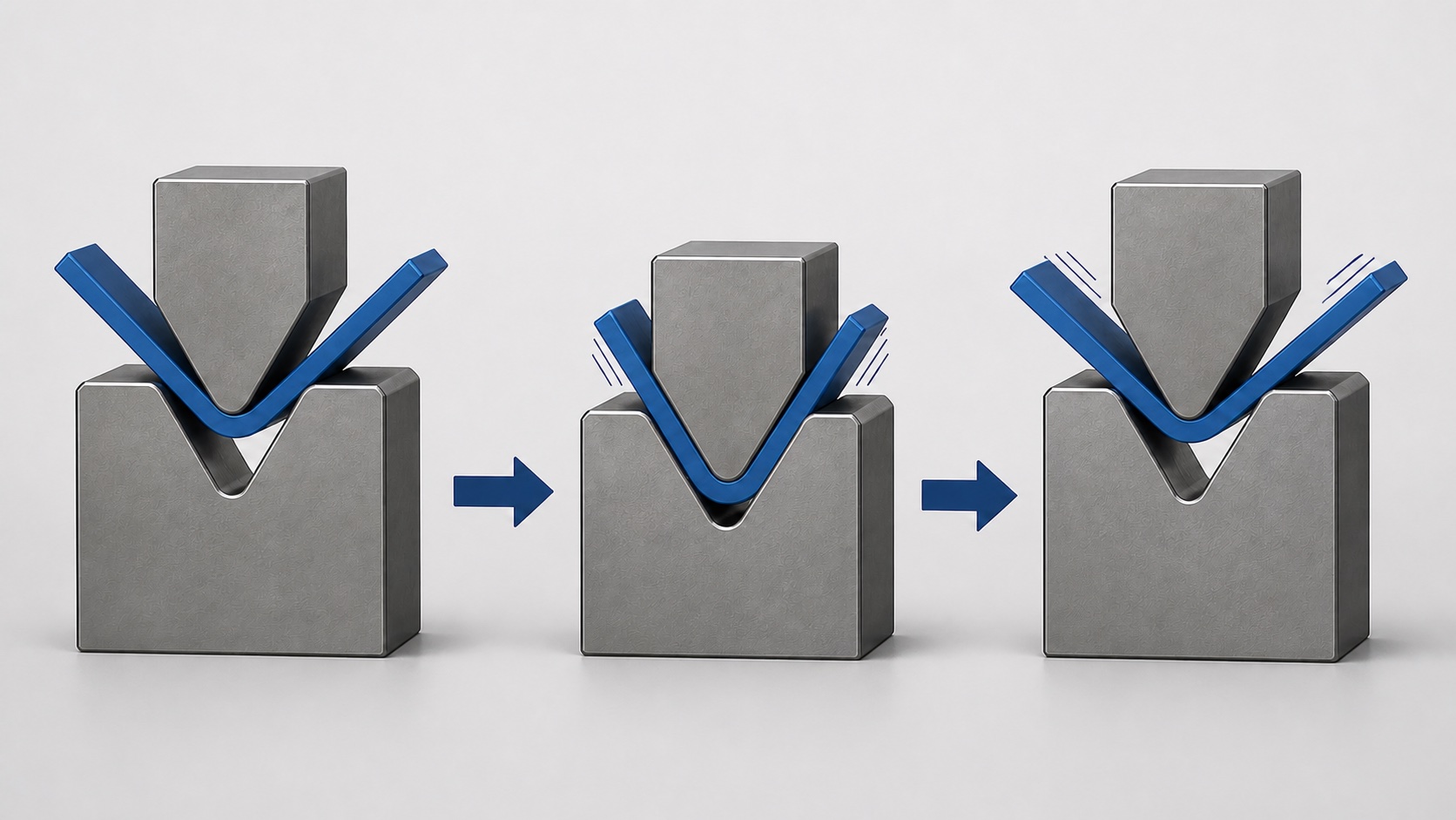
Accurate press brake angle control requires more than repeating the same ram position. The final released angle is the result of material behavior, actual thickness, rolling direction, punch and die geometry, machine deflection, forming depth and the way the angle is measured. The practical solution is to combine a controlled first bend with measured springback, small traceable corrections and, where justified, in-process angle feedback.
Technical scope: reviewed by COVO Engineering in August 2026 for air-bending setup and inspection. The article uses the uploaded three-stage springback diagram as its visual starting point and develops the subject into an original COVO production guide.


What is press brake angle control?
Press brake angle control is the process of predicting, measuring and correcting a bend so that the unloaded workpiece matches the specified angle. The CNC controls ram motion, but the customer accepts the finished part. A reliable setup therefore connects the programmed position to the measured released geometry.
The basic sequence is simple. The punch drives the sheet into the V-die, the material passes from elastic into plastic deformation, and the control stops at a calculated or corrected depth. When the punch retracts, the elastic portion of the strain recovers. The included angle normally opens and the inside radius may increase. This recovery is called springback.
Why does the bend angle change after unloading?
The outer fibres of a bend are stretched and the inner fibres are compressed. Some of that strain is permanent, while some remains elastic. After the load disappears, the elastic strain tries to return toward the flat condition. Higher strength, a larger radius-to-thickness relationship and a different material condition can all change the amount of recovery.
A common production example is a target released angle of 90 degrees. The press may need to form the part to 87.5 degrees under load so that approximately 2.5 degrees of springback opens it to the target. That number is only an example. A different coil, thickness, V-opening, punch radius or rolling direction can require a different correction.
For the underlying relationship between elastic recovery, neutral-axis position and flat development, read the COVO springback, K-factor and flat-length guide. The Springback Calculator provides a planning estimate, but the production value must come from the real setup.
Which variables cause press brake angle variation?
| Variable | Why it changes the angle | What to verify |
|---|---|---|
| Yield and tensile strength | Stronger or differently tempered material can resist plastic deformation and recover differently after unloading. | Grade, certificate values, coil or heat, temper and first-piece result. |
| Actual sheet thickness | Thickness changes the contact geometry, required force and ram-depth relationship. | Measure the production sheet instead of relying only on nominal thickness. |
| Rolling direction and anisotropy | The sheet can respond differently when the bend line is parallel or transverse to the rolling direction. | Blank orientation, grain direction and the approved flat-layout rule. |
| Punch radius and V-opening | Tool geometry changes the naturally formed radius, contact points, penetration and springback response. | Actual punch model, nose condition, die opening and shoulder wear. |
| Material lot | Two lots sold under the same nominal grade can remain within specification while having different mechanical properties. | Keep material identity and approved corrections with the job record. |
| Machine and tooling alignment | Deflection, crowning, clamp seating or uneven tool height can make the angle vary along the bend. | Measure left, center and right; inspect alignment before applying a global depth change. |
| Surface and friction | Scale, lubricant, film, galling or a damaged die shoulder changes how the sheet slides during forming. | Cleanliness, surface-protection method and tooling condition. |
Why is the real inside radius not a perfect CAD arc?
A drawing usually represents the inside bend with one ideal radius. A real air-bent section is created by changing contact and strain through the stroke, so its profile may not be a mathematically perfect arc. The central area can be tighter while the transitions toward the flanges open gradually. The exact shape depends on the material and tool geometry.
This matters because angle, radius and flange position are connected. If the job requires a controlled radius rather than only an acceptable angle, do not correct the CNC depth alone. Measure the formed radius, confirm the selected V-opening and evaluate a matched punch or COVO radius tool.
How much ram-depth correction equals one degree?
An older air-bending shop heuristic estimates ram movement per degree as approximately V-opening divided by 200. For a 16 mm V-die, that gives 16 / 200 = 0.08 mm per degree. The relationship is useful for understanding why very small depth changes can noticeably alter the angle.
| V-opening | V / 200 heuristic | Use |
|---|---|---|
| 8 mm | 0.04 mm per degree | Initial scale awareness only |
| 12 mm | 0.06 mm per degree | Initial scale awareness only |
| 16 mm | 0.08 mm per degree | Initial scale awareness only |
| 24 mm | 0.12 mm per degree | Initial scale awareness only |
| 32 mm | 0.16 mm per degree | Initial scale awareness only |
This is not a universal formula or acceptance standard. The angle-depth curve is nonlinear and changes with tool angles, material strength, thickness, radius, friction and bending method. Use the machine control's approved correction process, move in small increments and measure after every change. Never use extra penetration to exceed the rated load of the punch, die, holder or press brake.
How should a shop control a press brake angle?
- Define the angle convention: state whether the drawing uses included, inside, outside, supplementary or bend-through angle.
- Lock the inputs: record grade, actual thickness, rolling direction, bend length, surface condition and material lot.
- Verify the tools: confirm punch radius, die opening, working height, interface, condition and rated linear load.
- Calculate a starting setup: use validated shop data, the machine database or controlled planning calculations.
- Bend a representative coupon: use the production material and the real working tool combination.
- Measure after release: check the angle only after the punch has retracted and the part is free of forming load.
- Measure along the bend: compare left, center and right when bend length or tolerance makes local variation important.
- Correct one variable at a time: separate ram depth, crowning, backgauge and flat-pattern changes.
- Save the evidence: store the released angle, correction, tool IDs, material identity and inspection method with the job.
The COVO sheet-metal angle measurement guide explains how to select a measuring range and avoid mixing inside, outside and reflex-angle conventions.
What in-process angle measurement systems are available?
Manual first-piece inspection remains common, but modern press brakes can measure the angle during the bending cycle and send a correction to the CNC. These systems reduce dependence on one predicted material value, although every method still has an application envelope.
| Method | How it works | Strengths | Points to review |
|---|---|---|---|
| Optical laser or camera | A projected line and camera calculate the changing flange angle without contact. | No marking contact; can provide real-time feedback and multi-point measurement. | Visibility, reflective surfaces, protective film, flange geometry and sensor access. |
| Tool-integrated contact sensor | Sensor discs or probes contact the sheet while it is being formed. | Direct tactile measurement; useful where optical conditions are difficult. | Compatible upper tool, contact locations, flange length and special-profile clearance. |
| Carriage-mounted probe | A movable unit measures at selected locations along the bend. | Can inspect more than one longitudinal position. | Cycle time, access, probe path and the geometry of already formed features. |
| Portable retrofit system | An external sensor and controller add angle feedback to a compatible existing press brake. | Potential upgrade path without replacing the machine. | Integration, calibration, guarding, control authority and supported tooling applications. |
TRUMPF describes both optical ACB Laser and tactile ACB Wireless systems that measure actual angle and springback, while LVD's Easy-Form Laser measures the bend and sends real-time corrections to the CNC. These examples show the two main closed-loop approaches; they do not mean one sensor method is ideal for every part.
What automatic angle control cannot correct
An angle sensor can adjust ram motion, but it cannot make a damaged die shoulder straight, remove a wrong backgauge datum, create missing tool clearance or bring an overloaded tool back within rating. It also cannot guarantee that a radius, flange position, surface finish or multi-bend assembly dimension is correct merely because one measured angle passed.
- If the angle changes from left to right, inspect alignment, crowning, tool seating and material support.
- If the angle is correct but the flange is wrong, inspect the gauge datum, blank size and bend-development data.
- If the angle drifts by material lot, update the material record and first-piece correction rather than hiding the change.
- If the surface is marked, inspect contact pressure, die shoulders, contamination and the approved mark-free method.
- If a return flange collides, solve the profile and sequence clearance before changing depth.
How does precision tooling improve angle repeatability?
Tooling cannot remove the metallurgy of springback, but it can reduce controllable variation. Consistent punch height, a stable nose profile, straight die shoulders, matched segments and clean clamping references make the relationship between ram position and formed geometry more repeatable. Worn or mismatched tools invalidate stored corrections because the contact geometry has changed.
COVO supplies standard and custom press brake punches, dies, holders, adapters and forming tools for multiple machine interfaces. For an angle-control review, provide the part drawing, target angle convention, material certificate, actual thickness, bend length, punch and die models, press-brake system and measurements from the released first piece.
Frequently asked questions
Why does a press brake bend open after the punch retracts?
The bend opens because part of the strain stored during forming is elastic. When the load is removed, that elastic portion recovers and increases the included angle. The amount depends on the real material, thickness, rolling direction, inside radius, V-opening and bending method.
How much should a press brake overbend a 90-degree part?
There is no universal overbend value. Start from validated shop data or a controlled estimate, bend a coupon from the production material, measure the released angle and correct the ram depth in small documented steps. Store the approved correction with the exact punch, die and material condition.
Why can two sheets with the same grade bend to different angles?
Nominal grade does not lock every mechanical property. Actual thickness, yield strength, tensile strength, temper, rolling direction and coil or heat variation can change the angle-depth relationship and springback even when the drawing and CNC program are unchanged.
Is press brake ram depth enough to guarantee the final angle?
No. Ram depth controls tool position under load, while the drawing normally specifies the released part. Tool wear, material variation, machine deflection and elastic recovery can all change the final angle, so the first piece must be measured after unloading.
What is the difference between optical and contact angle measurement?
Optical systems use a laser or camera to read the sheet without touching it. Contact systems use probes, sensor discs or tool-integrated elements that touch the workpiece. Each method has application limits related to flange geometry, surface condition, tooling, access and machine integration.
Can automatic angle control eliminate test bends?
Closed-loop angle control can reduce first-piece correction and compensate for some material variation, but it does not remove the need to verify tooling load, radius, flange position, surface quality, crowning, collision risk and the released part against the drawing.
Technical references
- Accademia della Piegatura: Controllare l'angolo, un lavoro tutt'altro che semplice - the Italian technical discussion that prompted this independently written COVO guide.
- TRUMPF: TruBend Series 5000 angle measurement - official descriptions of optical ACB Laser and tactile ACB Wireless.
- LVD: Easy-Form Laser adaptive bending - official description of real-time angle measurement and CNC correction.
Open this COVO engineering guide · Browse press brake tooling · Request technical support