COVO KNOWLEDGE
Press Brake Springback, K-Factor and Flat Length: A Practical Guide
Published:
Last reviewed:
Learn how springback, neutral-axis position, K-factor, bend allowance and tooling choices work together to control press brake angles and flat length.
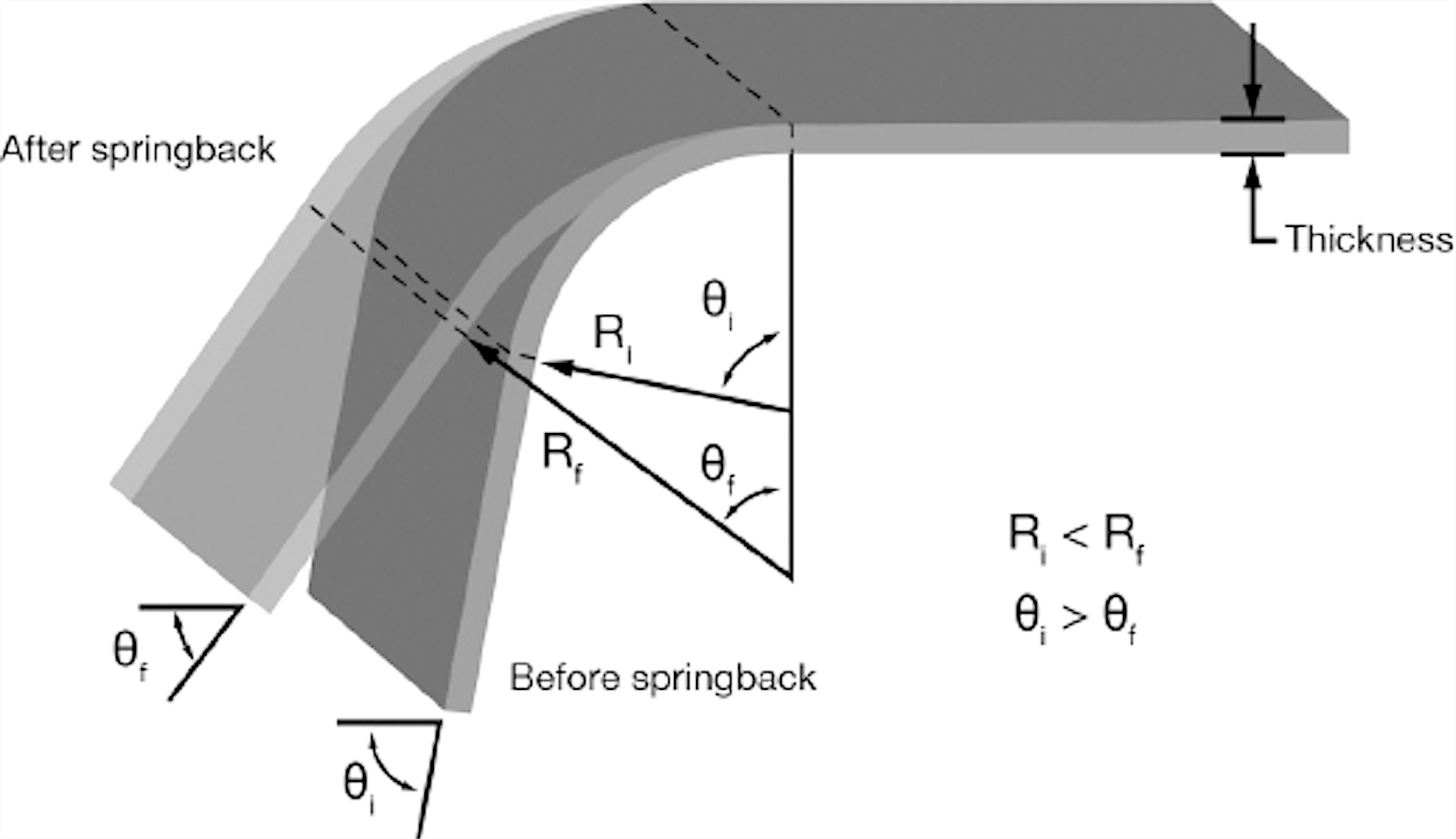
Springback is the elastic recovery that opens a sheet-metal bend after the press brake load is removed. The neutral axis and K-factor describe how strain is distributed through the bend, while bend allowance converts that behavior into a usable flat length. These three ideas must be handled together if a shop wants repeatable angles and dimensions.
This COVO engineering guide turns the core subjects of Chapter 4 in Sheet Metal Bending into a production workflow. It explains why a bend recovers, how air bending, bottom bending and coining change that recovery, where the neutral axis sits, how K-factor enters flat-pattern calculations and why a small error can multiply across a multi-bend profile.

What causes springback?
A bent sheet contains both permanent and recoverable strain. Fibres near the outside radius are stretched; fibres near the inside radius are compressed. Some of the deformation remains after unloading, but the portion that stayed within the material's elastic range tries to return toward its original shape. That elastic recovery produces the released angle and radius that the operator measures after the ram rises.
Springback is therefore not one fixed number for a material name. It changes with yield strength, tensile strength, thickness, rolling direction, material condition, inside-radius-to-thickness ratio, V-die opening, punch radius, bending method and the consistency of the sheet lot. Higher-strength steels and many stainless grades normally require more compensation than mild steel. Aluminium behavior depends strongly on alloy and temper. The only dependable production value is the one verified with the actual material and tool combination.
Overbending: the normal air-bending correction
Overbending means driving the workpiece to a slightly more acute angle than the target so elastic recovery brings it back to specification. For a nominal 90-degree part, the bottom-of-stroke angle might need to be less than 90 degrees. The required amount cannot be assigned from nominal material alone; it must be measured after the part has relaxed.
On a CNC press brake, the practical correction is usually a small change in ram depth or angle correction. Make one controlled change at a time. If the released angle varies along the bend, first inspect tool alignment, crowning, V-die condition and material consistency. A global depth correction cannot repair a local tooling or machine problem. COVO's Springback Calculator can provide a planning estimate, while the bending accuracy guide helps isolate material, tooling and machine causes.
Air bending, bottom bending and coining
Air bending
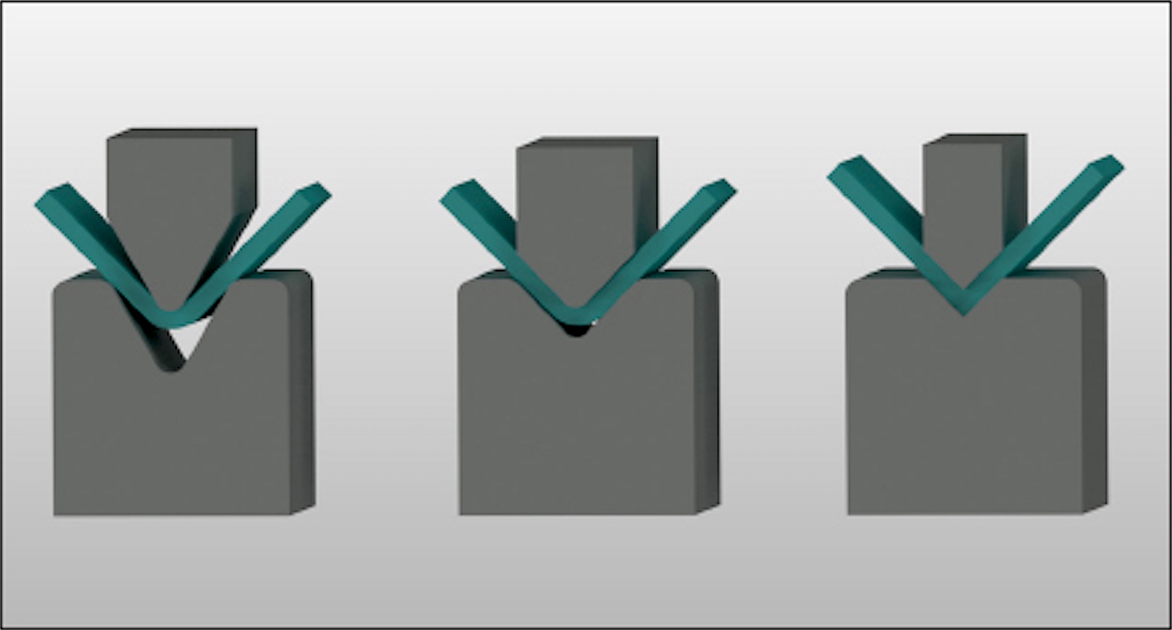
In air bending, the workpiece contacts the punch and the two die shoulders while remaining clear of the bottom of the V. The bend angle is controlled mainly by penetration depth. This method uses comparatively low force and one tool set can form several angles, which is why it is the dominant modern process. Its flexibility also means that material variation and springback appear directly in the released angle.
Bottom bending
Bottom bending brings more of the sheet into contact with the die faces near the end of the stroke. It can produce a stable result when punch and die angles are selected for the expected recovery, but it requires a matched setup and more force than ordinary air bending. The operator must distinguish controlled bottoming from an accidental overload at the bottom of the die.
Coining
Coining compresses the material between closely matched punch and die surfaces. The high local pressure plastically sets the bend and can greatly reduce springback, but the required force can be several times higher than air bending. Tool rating, holder rating and press-brake capacity must all be checked before this method is considered. Do not attempt to eliminate springback by increasing force beyond the approved load path.
For a side-by-side process discussion, see COVO's press brake bending methods guide. When a new setup changes bend length, material or V-opening, verify the required load with the Bending Force Calculator and the actual tooling ratings.
Neutral axis: the link between deformation and flat length
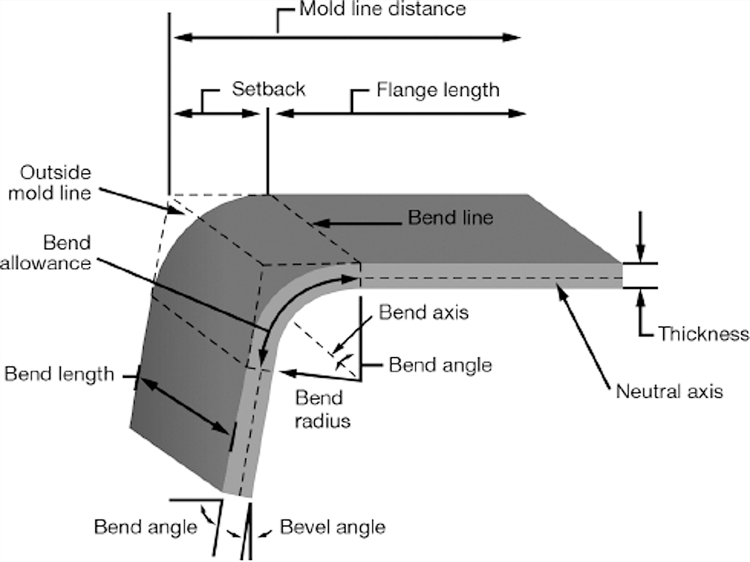
The outer part of a bend is in tension and lengthens. The inner part is in compression and shortens. Between them is a theoretical layer whose longitudinal length changes very little: the neutral axis. Its position is usually inside the mid-thickness of a typical sheet-metal bend, but it moves as material and geometry change.
The neutral axis matters because the arc length measured along it is used as the bend allowance. If the assumed axis is too close to the inside surface, the developed blank will be too short; if it is too far out, the blank will be too long. The error may be small on one bend and still become unacceptable after several bends.
What is K-factor?
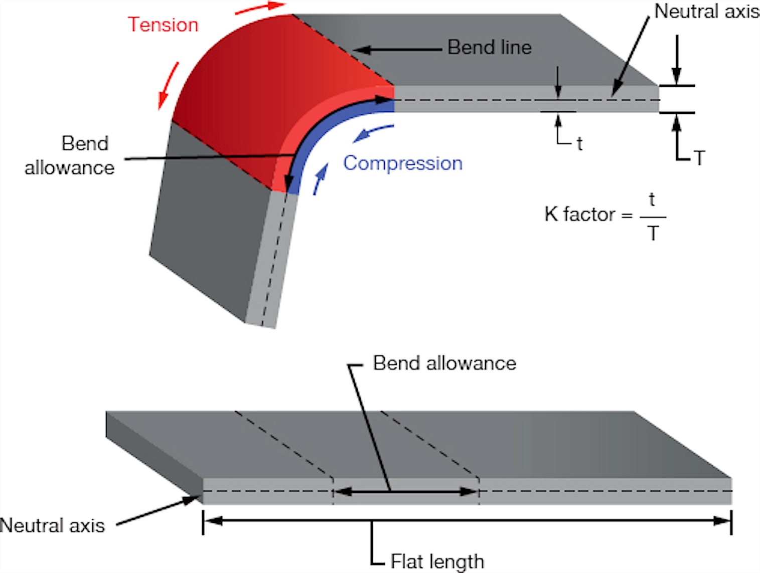
K-factor is the ratio between the neutral-axis depth and the material thickness:
K = t / T
Here, t is the distance from the inside surface to the neutral axis and T is sheet thickness. A K-factor of 0.33 means the neutral axis is assumed to lie about one third of the thickness from the inside surface. K-factor is not a permanent certificate value for a steel grade. It is an effective process value influenced by the radius-to-thickness ratio, bending method, tooling and real material response.
Practical starting values by radius-to-thickness ratio
- R/T up to 1.0: K about 0.30 as an initial estimate.
- R/T from 1.0 to 1.5: K about 0.35.
- R/T from 1.5 to 2.4: K about 0.40.
- R/T from 2.4 to 3.8: K about 0.45.
- R/T above 3.8: K approaches 0.50.
These values are useful for planning and for understanding the trend: as the inside radius becomes large relative to thickness, the neutral axis tends to move toward the middle of the sheet. They are not a substitute for a bend database or a validated test coupon.
Bend allowance and flat-length calculation
For one bend, the developed length can be viewed as the sum of the straight flange portions plus the arc length along the neutral axis. A common bend-allowance expression is:
BA = (pi / 180) x A x (R + K x T)
In this expression, BA is bend allowance, A is the included forming angle used by the selected calculation convention, R is inside radius, K is K-factor and T is thickness. Angle conventions differ between drawings and software, so define whether the input is bend angle, included angle or complementary angle before using a formula.
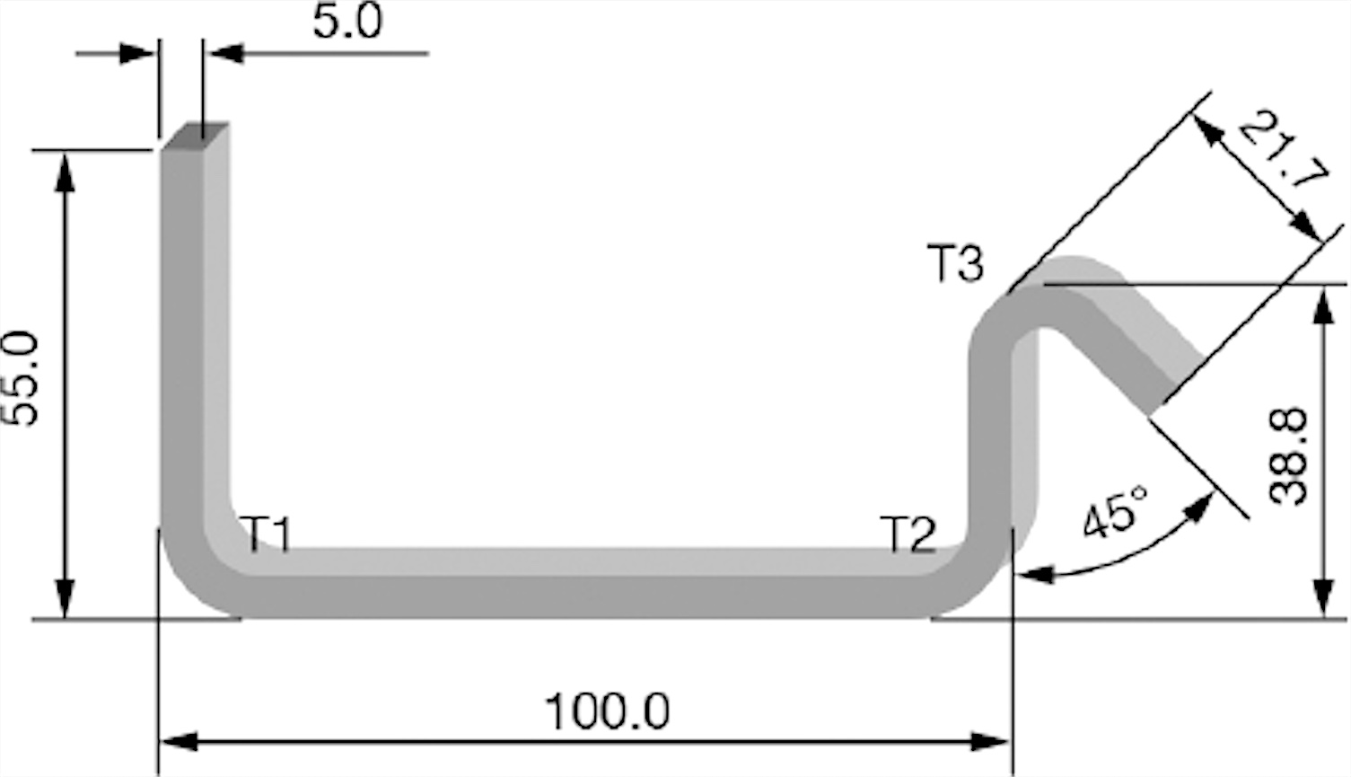
For typical air bending of mild steel, inside radius is often estimated near V/8. This is a useful starting approximation, not a universal rule. Material strength, die geometry, punch radius and the bending method can move the actual radius. Use the V-Opening Calculator and Radius Air Bending Calculator for preliminary planning, then measure the first approved bend.
COVO's Bend Allowance Calculator and Bend Deduction Calculator support both common planning routes. The related bend development guide explains how leg dimensions, press-line position and flat length connect.
Why small errors multiply across multiple bends
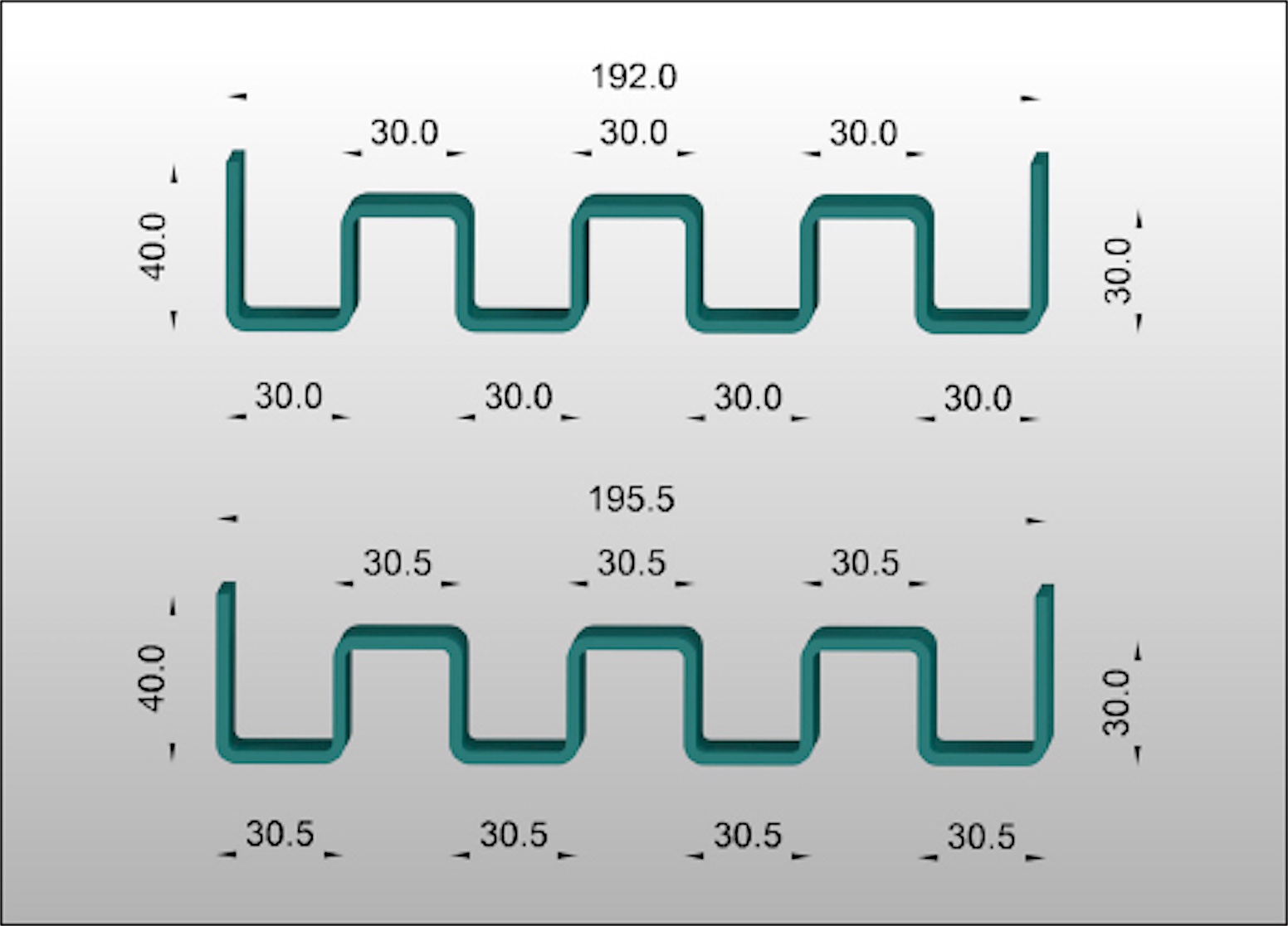
A discrepancy of only a few tenths of a millimetre at one bend can appear harmless. Across a repeated corrugated or channel profile, the same offset can accumulate at every pitch and move the final overall length by several millimetres. The drawing should therefore identify which dimensions are critical and where any permitted error may be relieved.
Do not automatically push all error into the final flange. The correct relief location depends on how the part fits its mating components. For contract work, the drawing or customer approval should define the functional datums. The press-brake operator can then control the first bend, measure the partial profile and place the remaining correction where it has the least effect on assembly.
A repeatable COVO workflow
- Lock the inputs: record material grade, actual thickness, rolling direction where relevant, bend length and surface requirement.
- Identify the process: choose air bending, bottom bending or a special forming route and state the intended inside radius.
- Define the tooling: record punch model and nose radius, V-die opening, shoulder geometry, tool height and the compatible tooling system.
- Calculate the starting values: estimate springback, force, K-factor, bend allowance and flat length using one documented convention.
- Run a representative coupon: use production material and the real working tool combination. Measure the released angle, inside radius and critical flange dimensions.
- Correct one variable at a time: separate depth, backgauge, crowning and flat-pattern changes so the cause remains traceable.
- Store the approved setup: keep the tool combination, material lot or family, controller correction, allowance or deduction and inspection result with the job.
Tooling choices that support stable results
Stable bend data depends on stable tooling geometry. A worn punch nose, damaged die shoulder or inconsistent V-opening changes the radius and the angle-depth relationship, which invalidates the stored springback and flat-length correction. Inspect working surfaces and clamping references before changing the program.
COVO supplies system-matched punches and dies for AMADA, TRUMPF, WILA, LVD and BYSTRONIC-style press brakes. For demanding radii or profiles, review radius tooling, forming tools and adjustable dies alongside the calculation.
Frequently asked questions
What is springback in press brake bending?
Springback is the elastic recovery that occurs after the press brake load is released. The bend usually opens and its inside radius may increase, so the programmed forming angle must compensate for the measured recovery of the actual material and tooling setup.
What is the neutral axis in sheet metal bending?
The neutral axis is the layer through the bent thickness where longitudinal strain is approximately zero. Material outside it is in tension, material inside it is in compression, and its position is used to calculate bend allowance and flat length.
What does the K-factor represent?
The K-factor is the distance from the inside bend surface to the neutral axis divided by sheet thickness. It is a process-dependent input for bend allowance, not a universal material constant.
Does a larger V-die opening change springback and flat length?
Yes. A different V-opening changes the naturally formed inside radius, the contact geometry, required depth and often the released angle. That also changes the bend allowance or deduction used for the flat pattern.
Which bending method gives the least springback?
Coining generally suppresses springback more than bottom bending or air bending, but it requires far more force and purpose-matched tooling. Air bending is the most flexible method, so its springback is normally controlled through depth correction and measured setup data.
How should a shop establish a reliable bend allowance?
Start with a calculated value, then bend a representative coupon using the production material, punch, die opening and method. Measure the released part and store the approved allowance, deduction or correction with that exact setup.
Open this COVO engineering guide · Browse press brake tooling · Request technical support