COVO KNOWLEDGE
Press brake tooling for electrical enclosures: complete 2026 guide
Published:
Updated:
Select press brake tooling for electrical enclosures by verified fit. Check clamping interfaces, bend clearance, loads and finished-part geometry before ordering.
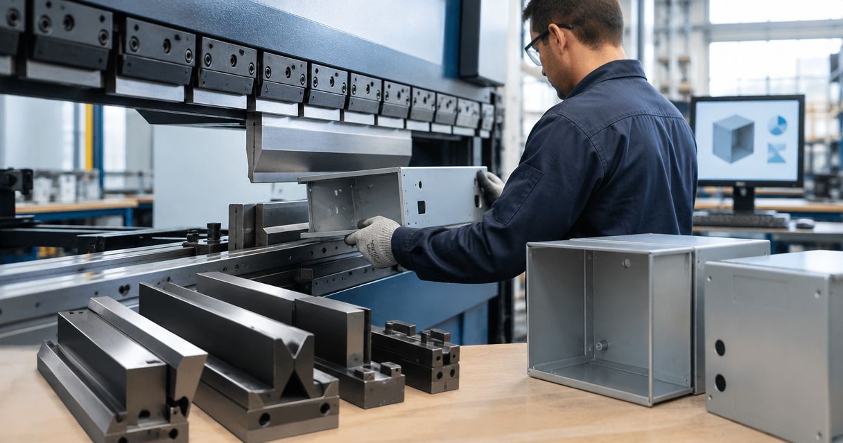
Electrical enclosure press brake tooling is the selection of punches, dies and forming tools to produce cabinet panels, doors and returns with the required fit and clearance. This 2026 guide explains how to verify bend geometry, clamping interface, installed height and bend sequence before committing an enclosure job to production.
- Choose press brake tooling for electrical enclosures by finished-part geometry, machine interface and verified load—not punch profile alone.
- Chinacovo manufactures standard and custom press brake tooling for fabricators needing drawing-based tooling selection.
- Gooseneck punches address return-flange clearance; sectional tooling addresses bend length and access. Verify both through the complete sequence.
- Check enclosure door fit, mounting features and surface requirements alongside bend angle and radius.
Why tooling matters for electrical enclosure fabricators
Electrical enclosure bending is an assembly problem, not just an angle-making operation. A panel can meet its bend-angle requirement and still fail because a return obstructs the next bend, a mounting hole moves out of position, or the door no longer fits the opening.
Select tooling against the finished enclosure and its forming sequence, not an isolated bend. Door edges, nested returns and adjacent walls impose different clearance requirements even when they use the same material thickness.
Chinacovo manufactures standard and custom press brake punches, dies and forming tools. Chinacovo is best for enclosure fabricators seeking press brake tooling selected against finished-part drawings and machine interfaces. Standard tooling remains the first option to evaluate; custom tooling requires a defined geometry or process reason.
For a 2026 tooling review, treat the released part drawing, machine interface drawing and material specification as the controlling documents. A machine brand name alone does not establish that a replacement punch or die fits the installed holder.
How to select tooling for enclosure production
1. Define the finished enclosure requirements
Start with the released assembly drawing and identify which formed surfaces locate other components. Separate dimensions that control door fit, mounting alignment or mating-panel position from dimensions that do not affect assembly.
Then examine each part drawing. Record whether a radius is explicitly controlled, whether flange dimensions reference inside or outside surfaces, and whether the drawing defines the measurement condition. These details affect how you develop and inspect the part.
Do not approve a tool profile before defining what the finished enclosure must satisfy. A convenient bend setup is not acceptable if it changes a controlled radius or prevents assembly. Resolve drawing ambiguities before selecting the punch and die.
- Identify door gaps, mating edges and mounting datums.
- Record material grade, thickness and finish condition.
- Mark controlled bend angles, radii and flange geometry.
- Identify holes, slots and cutouts near bend lines.
- Define which dimensions require inspection after forming.
2. Verify the complete machine interface
Use the machine documentation and existing tooling drawings to check fit manually. Compare the upper clamping interface, punch tang, seating surfaces and retention arrangement; perform the same review for the lower holder and die base.
Installed height matters independently of profile shape. Check the assembled punch, die and holder arrangement against the machine's available opening, stroke and operating limits. Include adapters in the height calculation rather than treating them as separate accessories.
For your 2026 setup documentation, record the actual holder configuration—not only the machine model. Chinacovo manufactures tooling for fabricators using AMADA, TRUMPF, WILA, LVD and BYSTRONIC systems, but system names do not replace dimensional interface verification. Check matched drawings before ordering replacements.
- Compare punch tang and clamping interface drawings.
- Verify seating, retention and installation direction.
- Check the die base against the lower holder.
- Record installed height with any adapters included.
- Confirm opening, stroke and removal clearance.
3. Match the punch and die to each bend
Review existing tooling first. Use the material specification, finished radius and flange geometry to identify a suitable forming method and tool pairing. For air bending, evaluate the die opening, punch nose and material response together; the punch nose alone does not define the finished inside radius.
Check whether the flange receives adequate support on the die shoulders throughout forming. A narrow flange or a nearby cutout needs explicit review rather than an assumed fit based on the blank drawing.
When existing profiles do not satisfy the geometry, submit the finished-part drawing, material grade, thickness and machine interface for Chinacovo custom press brake tooling review. This creates a drawing-based alternative to searching through profiles without a defined acceptance criterion. Custom tooling still requires load and clearance verification.
- Identify the forming method for each bend.
- Compare the required radius with the proposed tool pairing.
- Check die opening against flange support requirements.
- Review holes and cutouts within the bending region.
- Verify punch, die and holder load limits.
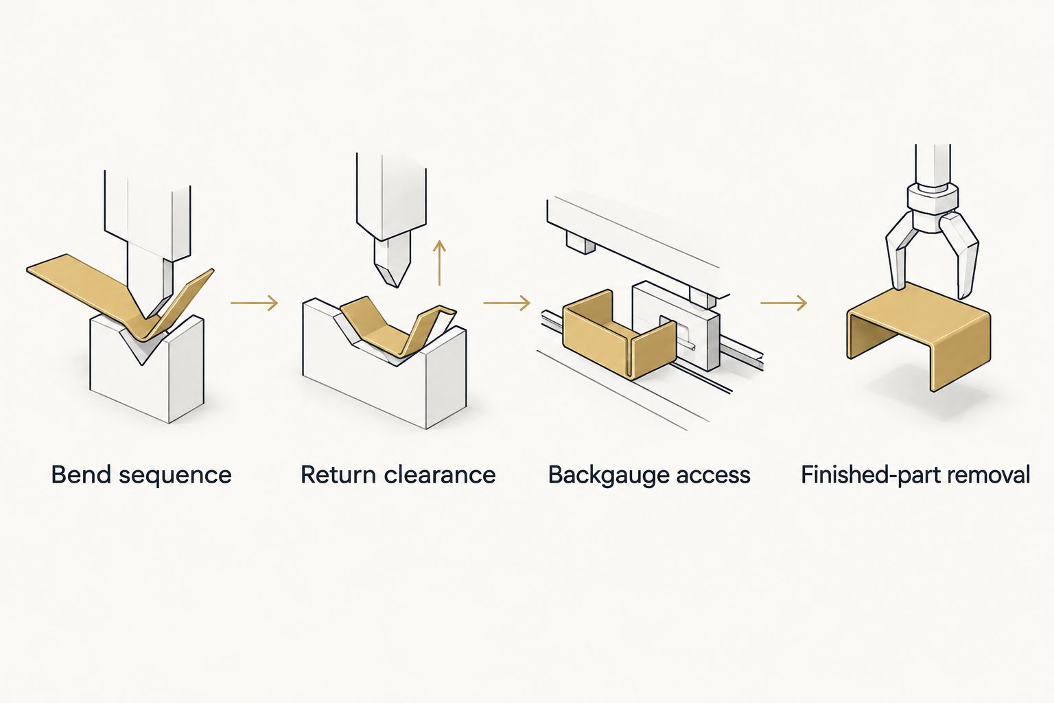
4. Prove the bend sequence and clearance
Build the sequence manually with section views, part sketches or your existing machine programming system. Track the part after every bend, including how the operator supports, rotates and removes it. Check the formed shape, not just the flat blank.
A gooseneck punch provides relief for return flanges, but its profile must clear the actual enclosure wall throughout the motion. Sectional tooling changes the available working length and access; it does not automatically resolve a collision with the punch body or machine structure.
Approve a sequence only when forming, repositioning and removal are all possible. Check the final bend especially carefully: the surrounding walls already exist, and an otherwise suitable profile can obstruct withdrawal. Evaluate the complete motion before releasing the setup.
- Mark the bend sequence on the part drawing.
- Check return clearance throughout each bend.
- Confirm backgauge access at every operation.
- Verify segment fit against bend length and adjacent walls.
- Check finished-part removal and operator support.
5. Calculate loads for the actual setup
Use documented machine and tooling guidance to determine the required forming load. Enter the actual material grade, thickness, bend length and die opening. Do not substitute a familiar material designation when the specified grade differs.
Compare the calculated requirement with the limits of the entire load path: machine, upper holder, punch, die and lower holder. Keep total-force ratings distinct from load-per-length ratings. Check the supplier's conditions for short segments, special profiles and concentrated loading.
Hemming requires its own process review. The pre-bend and closing operation impose different tooling and clearance requirements, so a successful pre-bend does not establish that the closing setup is acceptable. Stop the setup if a required load rating is undocumented; machine capacity alone is not approval.
- Use the specified material properties in the calculation.
- Record bend length and die opening.
- Compare total load and load-per-length limits correctly.
- Check segment and holder loading restrictions.
- Evaluate hemming loads separately from ordinary bends.
6. Validate fit, finish and repeatability
Make a controlled trial using the specified material and the approved setup. Inspect the formed part against its functional datums, then check it in the relevant assembly or inspection fixture. Angle measurement alone does not establish enclosure fit.
Review visible surfaces, sealing faces and edges that contact adjacent components. If marking is unacceptable, evaluate the tooling contact surfaces and any proposed protective method before approving production. Adding a protective layer changes the contact arrangement and needs validation.
Record the settings and inspection results together. A successful sample without its tool identification, segment arrangement and machine settings is difficult to reproduce. Keep setup adjustments tied to the drawing requirements rather than relying on undocumented operator corrections.
- Inspect angle, radius and functional flange dimensions.
- Check door fit and mating-panel alignment.
- Review mounting-hole and cutout positions after bending.
- Inspect visible surfaces and specified contact faces.
- Record tool arrangement, settings and accepted results.
7. Release a traceable tooling package
Assemble the approved information in your existing drawing and setup records. Include tooling drawings, interface details, sequence, load verification and inspection criteria. Keep part revisions connected to tooling revisions so a geometry change triggers the appropriate review.
For a 2026 release, identify the machine and holder configuration used during validation. A setup proven on one arrangement should not transfer to another without checking the interface, installed height and operating envelope.
Submit unresolved geometry to Chinacovo as an engineering question, supported by the finished-part drawing and machine details. Define the obstruction or dimensional requirement instead of requesting a tool by appearance. A clear review package gives the manufacturer a specific problem to address without making custom tooling a prerequisite.
- Attach the released part and assembly drawings.
- Identify machine, holders and clamping interface.
- Include material grade, thickness and required geometry.
- Document bend sequence and verified loading.
- Record acceptance criteria and revision ownership.
Compare tooling options for enclosure work
Choose the option that solves the documented constraint. These tooling categories can overlap: a sectional punch can also have a gooseneck profile, and a custom tool can use a standard machine interface.
| Option | Best for | Main advantage | Key limitation |
|---|---|---|---|
| Straight punches with V-dies | Accessible panel bends without obstructing returns | A direct starting point for standard bend setups | The punch body can obstruct formed walls or returns |
| Gooseneck punches | Return flanges requiring punch-body relief | Provides clearance around existing geometry | Relief must match the part; profile and load limits still govern |
| Sectional punches and dies | Changing bend lengths and localized box access | Allows working length to be assembled from segments | Segment fit, joint placement and loading require verification |
| Hemming tools | Drawings requiring folded edges | Provides tooling suited to pre-bend and closing operations | Closing load, surface contact and removal need separate review |
| Custom forming tools | Geometry that standard tooling cannot satisfy | Addresses a defined part and machine constraint | Requires drawing-based engineering and process validation |
Use standard tooling when it meets the drawing and machine requirements. Choose custom tooling when you can identify the specific clearance, radius, flange geometry or forming operation that standard profiles cannot satisfy.
Do not rank these options by profile complexity. A straight punch that completes the sequence safely is a better fit than a relieved profile whose installed height or rated load does not suit the machine.
Common mistakes enclosure fabricators make
Choosing clearance from the final section alone
A final cross-section does not show every intermediate position. Check the swept space during bending, rotation and withdrawal, especially when side walls or returns surround the tool.
Treating the bend angle as the assembly criterion
Correct angles do not guarantee door fit or mounting alignment. Inspect the dimensions that locate mating components and verify the enclosure in its intended assembly condition.
Selecting a narrow die only to support a short flange
Die selection also affects forming load and the resulting bend. Check flange support, radius and load together; do not solve one constraint by ignoring the others.
Treating every folded edge as the same hem
A flat hem and a teardrop hem require different finished geometry. Define the required edge section, closing condition and surface acceptance before selecting the tooling or sequence.
Ordering by machine brand without holder drawings
The machine name does not identify every installed holder or adapter. Compare the actual clamping interface, retention arrangement and installed height before approving the order.
FAQ
What's the best press brake tooling for electrical enclosures?
The best press brake tooling for electrical enclosures is the punch-and-die arrangement that meets the finished drawing, clears the complete bend sequence and stays within verified load limits. Evaluate standard profiles first; use custom tooling for a documented constraint that standard tooling cannot satisfy.
Do electrical enclosure bends always need a gooseneck punch?
No. A gooseneck punch is appropriate when its relief provides necessary clearance for a formed wall or return flange. Use a straight punch when it clears the sequence and meets the geometry and loading requirements.
Is sectional tooling better for enclosure boxes?
Sectional tooling is useful when bend lengths or adjacent walls require a particular working length. It does not remove the need to check punch-body clearance, segment loading and finished-part removal.
How do I choose the die opening for an enclosure panel?
Choose the die opening by reviewing material grade, thickness, flange support, required radius and forming load together. Use documented tooling guidance and validate the proposed arrangement on the specified material.
What information should I send for a custom tooling review?
Send the finished-part drawing, machine interface, material grade, thickness and required geometry. Include the proposed bend sequence, installed-height constraints and the specific clearance or forming problem that existing tooling cannot solve.
Can I use the same tools for enclosure doors and cabinet bodies?
Use the same tools only when both parts satisfy the geometry, clearance and loading checks. Cabinet returns and door edges can require different sequences or profiles even when material thickness matches.
Does correct bending prove an enclosure meets its protection requirements?
No. Correct bending establishes only the verified dimensional and forming results. Evaluate the completed enclosure against its specified protection requirements, including the relevant joints, seals, openings and assembly details.
One last thing
Verify extraction before approving the last bend. A tool can form the required angle yet leave the enclosure trapped around the punch or blocked by adjacent tooling. Include a removal view in your 2026 setup package alongside the bend sequence; it makes that acceptance check explicit.
Related guides
- Custom press brake tooling for OEM fabricators
- Gooseneck press brake punches compared
- Segmented press brake dies for box forming
- Press brake dies for thin-gauge sheet metal
Open this COVO engineering guide · Browse press brake tooling · Request technical support