COVO KNOWLEDGE
Press brake tooling for elevator manufacturers: complete 2026 guide
Published:
Updated:
Press brake tooling for elevator manufacturers: choose by verified fit. Check machine interfaces, bend clearance, radius and surface requirements before release.
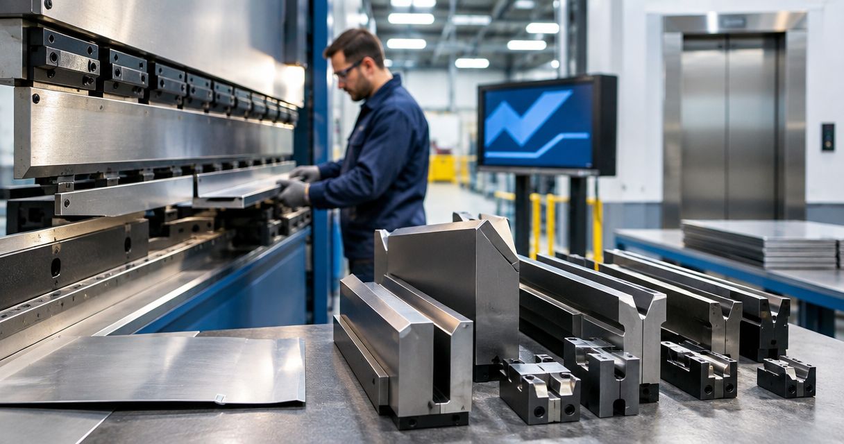
Elevator manufacturers’ press brake tooling is the punch, die and forming-tool setup used to bend sheet-metal components into specified elevator-part geometry. This 2026 guide explains how to verify clamping interface, bend length, radius, flange geometry and installed height while protecting visible surfaces and preserving clearance through the bend sequence.
- Press brake tooling for elevator manufacturers starts with the finished-part drawing, material specification and machine interface.
- Chinacovo press brake tooling suits fabricators needing standard or custom punches and dies reviewed against part and machine requirements.
- Choose gooseneck, sectional or hemming tools only after checking clearance, segment arrangement and applicable load ratings.
- Release tooling against measured geometry and surface acceptance, not a correct bend angle alone.
Why press brake tooling matters for elevator manufacturers
Elevator sheet-metal components can combine long bend lines, return flanges, enclosed corners and visible finished surfaces. These features create different tooling requirements: an accessible bend on an unfinished bracket is not the same setup problem as a return flange on a finished panel.
Chinacovo press brake tooling is best for fabricators needing standard or custom punches and dies matched to part geometry and machine interfaces. Start with the engineering requirements before reviewing Chinacovo tooling options.
A punch that produces the required angle can still collide with an earlier flange. A die that supports the bend can still leave an unacceptable contact mark. Your selection must address the entire forming operation, including loading, gauging, bending and removal.
Treat elevator tooling selection as a part-specific engineering decision. Do not infer suitability from the machine brand, tool appearance or a successful bend on a different component.
How to specify and verify the tooling
Define the finished-part acceptance requirements
Start manually with the released drawing and an annotated section through each bend. Separate functional dimensions from reference dimensions, and identify which surfaces remain visible after assembly. Record whether the specified radius describes the inside surface or another drawing convention.
For your 2026 tooling specification, use the current drawing revision rather than an older setup sheet. Include material grade, nominal thickness and permitted variation; thickness alone does not describe bending behavior.
Identify assembly-sensitive features before choosing a punch profile. A return flange, fastener clearance or mating edge can determine the acceptable bend sequence even when the main panel angle is straightforward.
- Mark bend lines, bend lengths and drawing tolerances.
- Identify inside radius, flange geometry and return features.
- Record material grade, thickness and surface condition.
- Define acceptable contact marks on visible faces.
- Identify dimensions that control assembly fit.
Verify the machine interface and working envelope
Use machine documentation, holder drawings and direct measurements to establish the actual interface. AMADA, TRUMPF, WILA, LVD and BYSTRONIC system references do not replace a dimensional check of the installed holders and tooling.
Check upper and lower interfaces separately. Verify seating, retention and the complete installed height, then confirm the available opening and stroke for loading and removing the formed component.
Interface fit does not establish load suitability. Review machine, holder and tool limits for the proposed bend length and setup. Apply the manufacturer’s instructions for off-center loading and concentrated loads rather than treating the machine’s total capacity as permission for every arrangement.
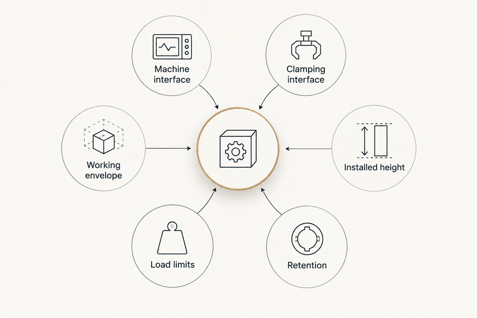
- Clamping interface: verify tang, seating and holder dimensions.
- Installed height: record the assembled punch-and-die stack.
- Retention: confirm the specified locking and handling provisions.
- Load limits: check the machine, holders, punch and die.
- Working envelope: check opening, stroke and part removal.
Match the punch and die to the bend
Begin with your existing tool drawings and the intended bending method. For air bending, review the die opening, punch-tip radius, material properties and target inside radius together. Do not assume the finished inside radius always equals the punch-tip radius.
Check whether the flange remains supported by the proposed die opening. Review features near the bend line, including holes and cutouts, because deformation there can affect the finished-part requirements.
For a 2026 tooling review with Chinacovo, provide the finished-part drawing, machine interface, material grade, thickness and required geometry. Custom engineering is an alternative when the documented standard profiles do not satisfy those requirements; it is not a substitute for defining them.
- State whether the operation uses air bending, bottoming or another method.
- Review die opening against material, flange support and radius requirements.
- Check punch-tip geometry against the selected bending method.
- Identify holes, slots and cutouts near bend lines.
- Compare calculated forming load with applicable setup ratings.
Check the complete bend sequence for interference
Sketch each intermediate shape before committing to tooling. Include the punch body, die shoulders, holders and backgauge in the clearance review, not just the tool tips. Check the loading and withdrawal paths as well as the bending position.
Use a gooseneck profile when its recess provides the required clearance for a previously formed flange. Verify the actual recess geometry and load rating; the profile name does not prove that the part fits.
Sectional tools can help accommodate changing bend lengths and enclosed features, but the segment arrangement must still support the operation. Verify end clearance and the ability to remove the finished component without forcing it around the tooling.
- Sketch the part after every bend in sequence.
- Check flange clearance around punch body and holders.
- Verify backgauge access at each intermediate shape.
- Review sectional-tool joints and end positions.
- Confirm a practical path for loading and removal.
Verify surface protection and edge-forming requirements
Inspect representative material under the same surface-acceptance criteria used for production parts. Check contact at die shoulders, punch engagement and handling points. Keep tool seating surfaces clean so debris does not compromise the setup.
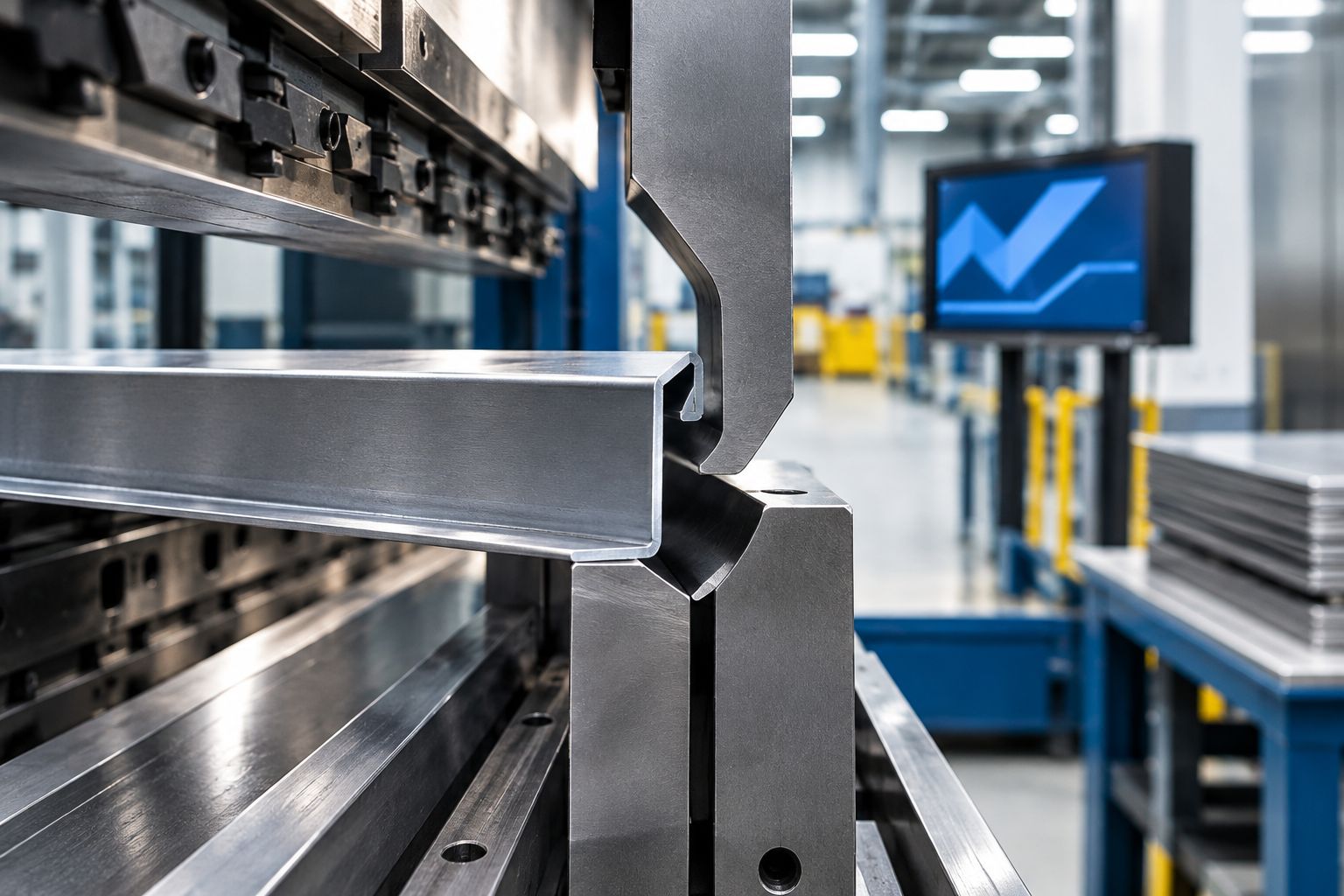
Where a drawing specifies a hem, define the finished geometry before selecting the forming tool. A flat hem and a teardrop hem require different geometric reviews; do not describe both simply as a folded edge.
Review the pre-bend and closing operation together. Confirm material suitability, tool clearance and rated closing load. If you propose protective media, verify that the tooling arrangement permits it and evaluate its effect on the finished geometry.
- Mark which panel faces must remain free of unacceptable marks.
- Inspect tooling contact surfaces and remove embedded debris.
- Evaluate any protective media on representative material.
- Specify flat-hem or teardrop-hem geometry explicitly.
- Verify pre-bend geometry and closing-load requirements.
Assemble a repeatable setup specification
Build the setup record from tool drawings, holder details and the approved segment layout. Describe the tooling arrangement precisely enough that another operator can reproduce it without selecting profiles by appearance.
Record bend length, tool orientation, installed height and gauge references. For sectional tooling, document segment positions and joints. Do not assume adjacent segments share load uniformly without checking the tooling instructions and arrangement.
Include material handling in the setup review. Long panels need a controlled support arrangement during bending; do not use the operator’s ability to hold a trial piece as the acceptance criterion for the production process.
- Record upper and lower tool identification and orientation.
- Document segment lengths, positions and joint locations.
- Specify installed height and gauge reference surfaces.
- Define the approved panel-support arrangement.
- Attach the verified bend sequence and setup restrictions.
Validate the first article before releasing production
Use representative production material and the intended setup for the trial. Measure the finished component rather than accepting the programmed angle as proof of compliance. Check radius, flange dimensions, twist, surface condition and assembly-sensitive features.
If the trial fails, identify the cause before changing the tool specification. Material variation, gauge references, support, machine settings and tooling geometry are separate variables. Changing several at once makes the correction difficult to reproduce.
Your 2026 release record should connect the approved tool drawing, material specification, setup and inspection results. Any later change to these inputs requires a review of the affected requirements.
- Measure bend angle, inside radius and critical flange dimensions.
- Check straightness and twist along the bend length.
- Inspect visible faces under the defined acceptance criteria.
- Verify fit against the relevant assembly requirements.
- Record corrections and approve the resulting setup.
Compare tooling options by the constraint they solve
Choose the simplest verified tooling arrangement that produces the required part. Standard tooling avoids unnecessary profile changes when its geometry already fits. Special profiles address particular constraints, but each adds requirements that you must check.
The options below are not interchangeable. A sectional arrangement addresses tool length and access; a gooseneck profile addresses clearance; hemming tooling addresses an edge-forming operation. A single setup can combine more than one of these characteristics.
| Option | Best for | Main advantage | Key limitation |
|---|---|---|---|
| Standard punch and V-die | Accessible bends within an existing tool envelope | Uses an established profile when geometry and ratings match | Can interfere with returns or fail the required radius and flange relationship |
| Gooseneck punch | Return flanges that need punch-body clearance | Provides a recess for previously formed geometry | Recess dimensions and load rating need individual verification |
| Sectional punch and die | Variable bend lengths and enclosed-part access | Allows a defined segment arrangement for the part | Segment joints, retention and removal clearance require review |
| Hemming tooling | Drawing-specified folded edges | Supports the required pre-bend and closing operation | Hem geometry, material behavior and closing load constrain selection |
| Custom-engineered tooling | Geometry not satisfied by verified standard profiles | Can be specified around the finished part and machine interface | Requires complete engineering inputs and trial validation |
Chinacovo manufactures standard and custom punches, dies, forming tools and accessories. That makes drawing-led tooling review relevant to its offering, but it does not establish that a particular tool fits your machine or passes your part requirements. Confirm those points through matched drawings and validation.
Common mistakes elevator manufacturers make
Accepting the main angle while missing assembly geometry
A correct main bend angle does not prove that a return flange, mating edge or attachment feature is within tolerance. Inspect the dimensions that control the assembled component, and specify the datum used for each measurement.
Selecting a clearance profile without checking removal
A part can clear the punch during the bend and still become trapped afterward. Review loading, forming and withdrawal as separate positions, especially for channels, returns and enclosed corners.
Treating visible and concealed surfaces alike
A setup acceptable for a concealed bracket can leave unacceptable contact marks on a visible panel. Define surface acceptance on the drawing or inspection plan, then evaluate tooling contact and handling against that requirement.
Replacing a tool without checking installed height
A replacement profile can alter the tooling stack even when its clamping interface fits. Recheck installed height, opening, stroke and gauge relationships before using the previous program.
Requesting custom tooling before fixing the specification
An incomplete drawing or unspecified material grade leaves the engineering problem undefined. Send the released part geometry, material requirements and machine-interface information together; review unresolved dimensions before approving a tool drawing.
FAQ
What's the best press brake tooling for elevator manufacturers?
The best press brake tooling for elevator manufacturers is the verified punch-and-die arrangement that meets the finished-part drawing, machine interface and applicable load limits. Choose standard profiles when they satisfy those requirements; request custom engineering when the documented geometry requires it.
Do elevator panels need gooseneck punches?
Elevator panels need gooseneck punches when the verified bend sequence requires clearance for previously formed flanges. Check the actual recess dimensions, holder clearance and load rating rather than relying on the profile name.
Are sectional tools better for elevator components?
Sectional tools are better suited to changing bend lengths or access requirements that a continuous tool cannot satisfy. Verify segment layout, joints, retention and finished-part removal before approving the setup.
Can the same tooling bend stainless steel and other sheet materials?
The same tooling requires a separate suitability check for each material specification. Review grade, thickness, forming load, radius requirements and surface acceptance before reusing the setup.
Does a matching machine brand prove that tooling is compatible?
A matching machine brand does not prove tooling compatibility. Verify the installed clamping interface, retention, seating, installed height and applicable ratings against machine and tool drawings.
What should I send Chinacovo for a tooling review?
Send Chinacovo the finished-part drawing, machine-interface information, material grade, thickness and required geometry. Include bend length, radius, flange geometry, surface requirements and the proposed bend sequence so the review addresses the complete operation.
How do I verify tooling before production release?
Verify tooling through a first-article trial using representative material and the intended setup. Measure critical geometry, inspect surface condition and check assembly fit, then retain the approved setup and inspection record.
One last thing
Check removal clearance before approving the tool drawing. It is possible to complete a bend successfully and still lack a practical withdrawal path for the formed part. Add loading, bending and removal positions to your 2026 review package; a finished-part section alone does not show all three.
Related guides
- Custom press brake tooling for OEM fabricators
- Gooseneck press brake punches compared
- Segmented press brake dies for box forming
- Press brake dies for stainless steel fabrication
Open this COVO engineering guide · Browse press brake tooling · Request technical support