COVO KNOWLEDGE
Deep U-Bending Tools and Press Brake Sequence Guide
Published:
Last reviewed:
Select tooling and plan bend sequences for deep U-channels by checking punch clearance, movable strips, part release, springback and first-article control.
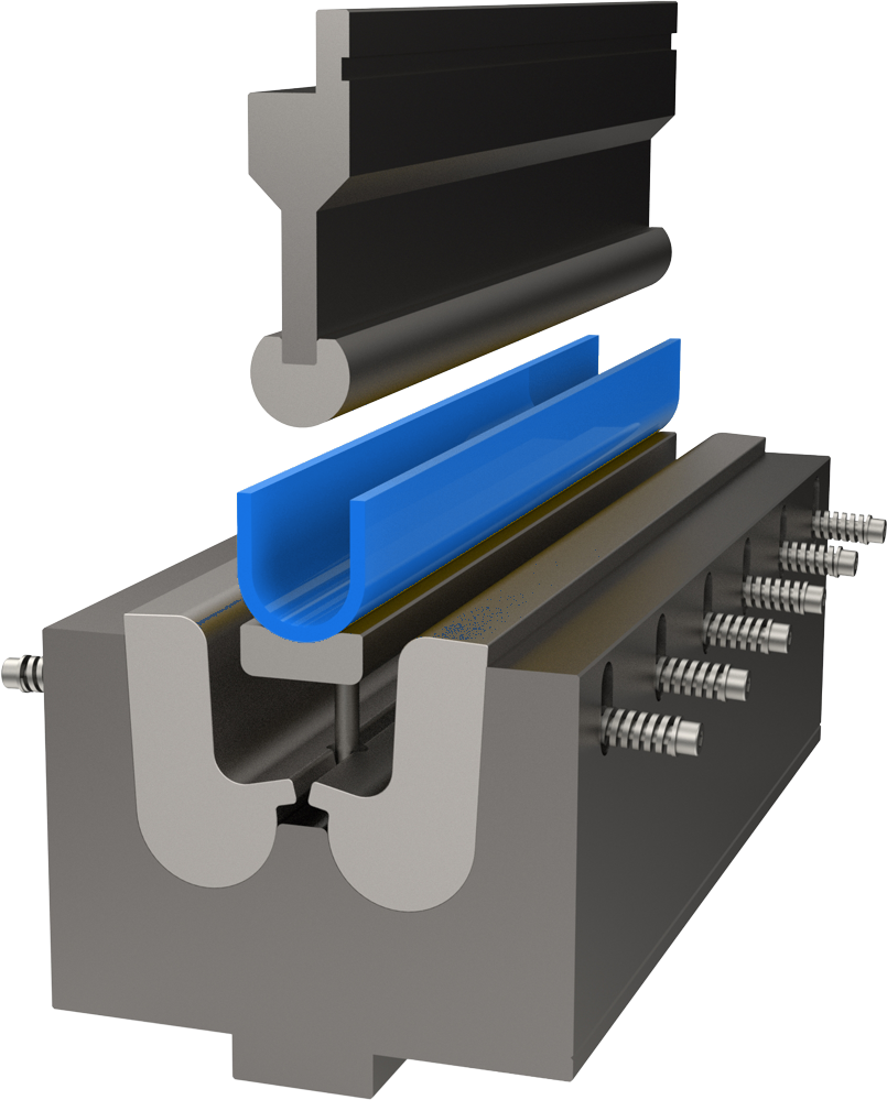
A deep U-bend is feasible only when the punch, die, machine and workpiece remain clear through both forming and removal. Start with the finished channel width, depth, inside radii and return direction, then evaluate the intermediate shape after each stroke. A standard V-bending setup may make the first side correctly but collide with the formed flange on the second side.


What is a U-bending tool?
A U-bending tool is a press brake punch-and-die arrangement developed to produce two approximately parallel side walls connected by a base. The term covers ordinary channels made by two V-bends as well as dedicated forming sets that create or calibrate the complete section. The important distinction is not the letter shape; it is how the tooling controls access, wall support, dimensional movement and part removal.
For a shallow channel, two independent air bends may be the most flexible route. For a deep or narrow channel, the first wall occupies the same space that the punch body needs during the second stroke. A dedicated solution changes that geometry through punch relief, moving die components or a sequence that preserves access until the final operation.
Define the finished U-channel before choosing tools
The tooling review begins with a dimensioned section. Record the clear inside width, outside width, base length, side-wall height, included angles, inside radii and any return flange. Mark which dimensions control assembly and which surfaces must remain free of die lines. Add material grade, actual thickness tolerance, grain direction, bend length and expected batch size.
Machine information is equally important. Confirm the upper and lower clamping system, available open height, stroke, throat, ram and holder profiles, die support width, rated load and usable bed length. A tall relieved punch may solve flange interference but consume open height; a wide forming die may fit the profile but overhang the lower support. The complete stack must be checked as one load path.
The standard two-bend U-channel sequence
- Form the first wall: gauge from a stable edge and make the first bend while the remainder of the blank is flat and easy to support.
- Reorient the workpiece: rotate or flip the part according to the second bend direction, preserving the approved visible face and datum.
- Verify clearance: check the first wall against the punch body, holder, upper beam, die and backgauge through the full rotation path.
- Form the second wall: complete the second bend and measure the released wall angle, channel opening, base width and squareness.
This route is efficient when the two side walls remain outside the tool envelope. It also allows standard punches and dies to serve several channel sizes. The limitation is that the second bend can pull the base, alter the first wall angle or create an inaccessible profile. The sequence must be simulated or dry-run with the actual tool geometry before production.
Clearance is a moving envelope, not one dimension
A common feasibility check compares channel depth with punch throat depth. That is necessary but incomplete. During air bending, the workpiece rotates around the die shoulders while the punch descends. The previously formed wall sweeps through an arc and may contact a holder even if it clears the punch at bottom dead centre.
Include the punch tip, punch body, shoulder, upper holder, adaptor, ram, die shoulders, lower holder, backgauge fingers and support equipment in the model. Check the loaded state, released state and withdrawal direction. Side flanges, weld nuts and tapered edges require a three-dimensional review because a clean centre section can hide an end collision.
When to use a gooseneck or relieved punch
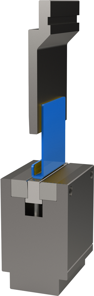
A gooseneck punch places the punch body away from the formed flange. It is often the first option for C-profiles and U-channels made with two bends. Choose the relief from the full flange height and return geometry, then confirm the tool's rated linear load. Removing material from the punch body creates clearance but also changes its strength and deflection behaviour.
Segmented punches can make a closed or boxed profile easier to remove. Taller punches or adaptors may move the workpiece away from the holder, although every added interface affects working height, alignment and load capacity. Browse compatible COVO punches, dies and adaptors, then verify the exact stack for the machine.
Movable strips and ejectors for deeper profiles
Movable bending strips rotate or translate as the tool closes. They support the sheet through the forming path, reduce the fixed obstruction beside the developing wall and return when the ram opens. A spring-loaded ejector can lift the finished channel away from the die so the operator does not have to pry a tight part from the tool.
These components must be sized for the material and load, guided against uneven movement and protected from scale or debris. The design should identify wear surfaces, lubrication points, return travel and a safe maintenance method. COVO reviews movable U-bending concepts under U-bending with movable strips and conventional sets under U-bending tools.
Staged forming when direct bending is blocked
Some deep profiles need more than two final-angle strokes. A pre-form can move material into a position that keeps the next bend reachable. A recovery sequence may partially form one side, complete the opposite side and then return to finish the first. A temporary opening bend can reduce the effective envelope of a very deep C-profile before it is straightened in the last operation.
Every extra stroke adds handling, potential marking and dimensional variation. Define the angle and datum for each intermediate state so the method can be repeated by another operator. The COVO bend-sequence strategy guide explains recovery bends, deep returns and collision-driven sequence choices in detail.
One-stroke U-forming versus two separate bends
| Decision factor | Two standard bends | Dedicated U-forming tool |
|---|---|---|
| Flexibility | One tool set can cover several channel widths. | Working profile is matched to a defined part family. |
| Setup cost | Usually lower for prototypes and short runs. | Higher engineering and tool investment. |
| Cycle | Two strokes plus reorientation. | One controlled forming cycle may be possible. |
| Dimensional control | Second bend can affect the first wall and base. | Both walls can be supported or calibrated together. |
| Clearance | Depends strongly on punch relief and sequence. | Moving components can be designed around the profile. |
| Best use | Variable work, open channels and smaller quantities. | Repeat production, deep profiles or strict section control. |
Die opening, radius and minimum flange checks
For two-bend air forming, select the V-opening from material, thickness, required inside radius, minimum flange and acceptable force. A larger opening reduces tonnage but increases the naturally formed radius and minimum flange. A smaller opening raises force and surface pressure. Use the COVO bending force calculator for a preliminary estimate, then confirm tool and machine limits.
A dedicated U-forming die follows a different contact pattern. Its load may be distributed across several working areas or concentrated during calibration. Do not apply a standard air-bending tonnage result directly to a special forming tool without an engineering review.
Control channel width, squareness and springback
U-channel acceptance normally requires more than two correct bend angles. Measure the opening at defined heights, base width, wall parallelism, diagonal or squareness, straightness along the bend and visible-surface condition. Springback can open both walls, while the second operation can translate the base or rotate the first wall.
Run the first article with production material and record the actual thickness, material batch, tool combination, stroke correction, backgauge datums and released measurements. Change one variable at a time. If both walls open consistently, adjust the process or calibration geometry; if one wall moves during the second stroke, review support, gauge reference and sequence before adding a generic angle correction.
First-article U-bending checklist
- Verify the drawing revision, material grade, thickness and grain direction.
- Confirm punch, die, holder and adaptor models against the approved setup.
- Check the complete intermediate workpiece envelope and final removal path.
- Verify minimum flange, bend radius, open height, stroke and rated linear load.
- Protect visible surfaces and clean all working shoulders before the trial.
- Support long panels so their weight does not twist either bend line.
- Measure both wall angles, channel opening, base width, squareness and straightness.
- Store the validated sequence and corrections with the job record.
Frequently asked questions
What tooling is used to form a deep U-channel on a press brake?
A deep U-channel may use a relieved or gooseneck punch, a matched U-forming die, movable bending strips, an ejector or a staged forming sequence. The correct option depends on channel width, depth, return geometry, material, bend length and the press brake opening.
Why can a standard straight punch fail on the second U-bend?
After the first side is formed, that flange can contact the punch body, holder or upper beam during the second bend. The bend line may be reachable at the tip while the complete workpiece sweep still collides with the tooling stack.
How do movable strips help U-bending?
Movable strips support the sheet during forming, move with the developing walls and open a release path after the stroke. They are useful when a fixed die would trap a deep profile or make part extraction difficult.
What information does COVO need to design a U-bending tool?
Provide the finished section, material grade, thickness, bend length, tolerances, visible surfaces, expected quantity, press brake model, clamping system, open height and any limits on part handling or tool segmentation.
Can a deep U-profile always be formed in two strokes?
No. Some profiles need pre-forming, a recovery bend, movable components or a dedicated one-stroke forming tool. Feasibility must be checked against every intermediate shape and the final part-removal path.
Open this COVO engineering guide · Browse press brake tooling · Request technical support