COVO KNOWLEDGE
Press Brake Bend Sequences: A Practical Strategy for C-Profiles and Deep Returns
Published:
Last reviewed:
Plan press brake bend sequences for short flanges, C-profiles, recovery bends, deep returns and long parts while reducing collisions and handling.
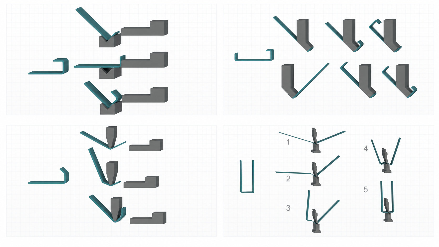
A press brake bend sequence is the planned order in which every bend of a sheet-metal part is formed. The strongest sequence is not simply the order shown on a drawing. It keeps every operation reachable, protects critical dimensions, reduces part rotations and lets the finished workpiece leave the machine without contacting the punch, die, ram or frame.
Bend sequencing is a strategy problem because every stroke changes the workpiece for the next one. The blank becomes more rigid, its centre of gravity moves, new flanges enter the machine envelope and previously formed surfaces become potential datums or collision points. This guide converts the complete logic of the referenced bend-sequence chapter into a production workflow for C-profiles, long components, recovery bends and deep returns.


What is a press brake bend sequence?
A bend sequence assigns an operation number, bend direction, tooling combination, datum and handling orientation to every bend line. It should answer five practical questions before the blank reaches the machine:
- Can the current bend be positioned accurately? The selected flange or edge must reach the backgauge or approved locating fixture.
- Can the tool reach the bend line? Existing flanges must clear the punch body, die shoulders, holders and machine structure.
- Can the operator support the part? Its weight, length and centre of gravity must remain manageable throughout the stroke.
- Will the operation preserve earlier work? A new bend must not flatten, twist or mark a previously approved feature.
- Can the part be removed? The finished geometry needs a safe withdrawal path after the ram opens.
There is rarely one universal order based only on shape. The same drawing can need a different sequence on another press brake, with another punch height, die width, backgauge range or handling system. Sequence planning therefore belongs to the complete manufacturing method, not only to CAD geometry.
The foundational rule: make short bends before long bends
The most useful starting rule is to form short bends and local fins while the sheet is still relatively flat, then create the long bends that give the part its final stiffness. A short flange is usually easier to present to the tool when the surrounding material can flex and lie on the supports. Once a long fold is made, the part behaves more like a beam or channel and becomes harder to rotate, gauge and clear.
This order also reduces the risk of a visible counter-bend. If a long bend is completed first and a nearby short flange is formed later, the rigid return may bear against the die or machine and force a secondary deflection close to the intended bend line. The result can be a wave, witness mark or local angle error even when the programmed stroke depth is correct.
Short-first is a rule of preference, not permission to ignore interference. A short bend should be delayed when completing it would trap the part, remove the only reliable datum or prevent the punch from reaching another bend. The complete intermediate geometry always decides.
Avoid wrapping the workpiece around the tooling
A sequence fails when the developing part surrounds the punch, holder or machine structure so that the next operation or final removal becomes impossible. This can happen gradually: each individual bend appears possible, but the combination closes the profile around the upper tool. C-shaped parts, narrow returns and box-like sections deserve particular attention.
Check more than the punch tip. The required clearance envelope includes the punch shoulders, upper holder, ram adaptor, machine upper beam, die body, lower holder, backgauge fingers and the full swept path of the workpiece as it rotates during bending. A section drawing can reveal basic conflicts, while a 3D model is more reliable for tapered parts, side flanges, weld features and non-symmetric blanks.
C-profile sequence and machine clearance
A simple C-profile normally uses two bends in the same direction, but its feasibility depends on the return depth, overall height and tool projection. After the first bend, that flange must pass beside the punch and holder during the second stroke. After the second bend, the completed channel must still clear the upper tool as the ram opens.
A gooseneck or relieved punch can create space for a return flange, but its load rating and throat geometry must match the job. Segmented punches may help with removal, while a taller tool can move the part away from the holder at the cost of open height and load-path considerations. When standard clearance is insufficient, compare the job with COVO custom forming tools.
The same three bends can support different valid sequences
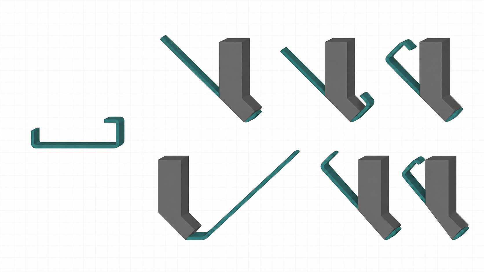
The illustration shows that one profile can be produced by several operation orders. For a short, light part, the preferred sequence may follow the easiest hand movement and the most direct backgauge access. The operator can rotate the workpiece quickly, so an extra turn has little effect on cycle time.
For a component longer than 10 metres, the decision changes. Turning the part may require several people, supports, a lifting device or a coordinated transfer. A theoretically elegant order can become the slowest and least safe route if it asks the team to rotate a long section after every stroke. The preferred sequence may instead keep one orientation for consecutive bends even if the local order differs from a small-part setup.
Batch size amplifies the difference. One extra rotation on a prototype is a minor inconvenience; repeated hundreds of times, it becomes a substantial handling cost and a source of fatigue-related variation. Sequence selection should therefore include total motions per part, support changes, gauge changes and the number of times the workpiece must be turned over.
Use stable datums and protect dimensional chains
Every bend should reference an edge or formed feature whose position is sufficiently stable for the required tolerance. Early operations can create useful datums, but they can also consume the flat edges that the backgauge needs. If a tight dimension spans two or more bends, choose a sequence that limits the number of independent gauge settings inside that chain.
Place the most critical relationship under direct control whenever possible. For example, if a return flange must fit an assembly, gauge from the feature that controls that fit instead of allowing several earlier bends to accumulate into its location. Record whether the dimension is checked in the loaded or released condition, because springback can change the final datum position.
Recovery sequences for adjacent bends
A recovery sequence deliberately returns to an earlier bend. The first bend is made only far enough to create access or establish the developing form. A second bend is then completed, and the workpiece returns to the first station or orientation so the original bend can be closed to its final angle.
This technique is useful when completing the first bend immediately would force a neighbouring flange beyond 90 degrees, remove backgauge access or create a dimensional error at the next bend. A small angular error in the first flange can create a much larger positional difference at the second bend line because the error is magnified over the flange length. Completing the first bend after the adjacent geometry exists can make the final relationship easier to control.
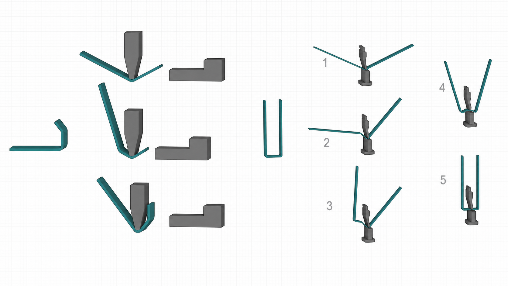
A recovery sequence is not a free correction. It adds a stroke, a handling step and another opportunity for marking or misalignment. Use it when the improvement in access or tolerance is worth that cost, and document the partial angle so another operator can reproduce the method.
Deep C-bends: use a temporary central bend to create clearance
A deep C-section may be impossible to close with a direct outside-to-inside order because the long side wings collide with the upper beam before the final return can reach the tools. One practical strategy is to introduce a temporary, open bend near the centre of the blank. This false bend shortens the effective width and changes the orientation of the wings during the side operations.
- Create the temporary central bend: form an open angle that brings the side wings into a machine-compatible envelope.
- Make the first lateral bend: use the temporary geometry to clear the upper structure.
- Reorient the workpiece: support the developing section without damaging the first side.
- Make the second lateral bend: complete the opposite return while the central relief still provides clearance.
- Straighten the temporary bend: flatten the centre carefully to produce the specified deep C-profile.
The chapter presents an initial opening around 150 to 155 degrees as a practical concept, depending on side-wing height. A more acute temporary bend is harder to straighten and may leave visible evidence or residual stress. In some layouts, approximately 145 degrees can provide additional clearance from the press brake upper beam. These values are not machine settings for every job: the angle must be derived from the actual wing height, tool stack, opening, material and machine geometry.
Straightening also needs an approved method. Confirm where the part is supported, which face may contact the tool and whether the recovered surface has a flatness or appearance requirement. A temporary bend across a visible panel may be unacceptable even when it solves the collision problem.
A repeatable bend-sequence planning workflow
- Read the finished drawing: mark every bend line, direction, included angle, inside radius, critical tolerance, visible face and assembly datum.
- Define the process: record material grade, actual thickness, grain direction, bend length, expected springback and quantity.
- Select candidate tools: check punch relief, nose radius, die opening, working height, segment lengths, holders and machine interface.
- Start with constrained features: identify short flanges, closed returns, deep walls and bends that will become inaccessible.
- Build intermediate states: model the part after each stroke rather than checking only the flat and finished forms.
- Run collision checks: include the workpiece sweep and all machine structures, not only punch-to-part contact.
- Evaluate handling: count rotations, flips, support changes, operators and lifting-device movements.
- Evaluate measurement: assign a stable datum and inspection method to each critical dimension.
- Verify force and flange limits: confirm minimum flange, tonnage, tool load and local load concentration with the selected setup.
- Approve a first article: run production material, inspect the released geometry and store the verified sequence with the program.
The COVO Bending Force Calculator helps establish a preliminary load for standard bends. Sequence, local loading and special forming geometry still require a complete application review.
How to compare two feasible sequences
When collision checking leaves more than one option, score each sequence against the same production criteria:
| Criterion | Question to ask |
|---|---|
| Collision margin | How much verified clearance remains at the closest point of every stroke? |
| Handling effort | How many rotations, flips, support changes and assisted lifts are required? |
| Datum stability | Does each operation gauge from a flat, repeatable and undamaged feature? |
| Tolerance accumulation | How many independent bends contribute to each critical finished dimension? |
| Surface protection | Will a visible face slide on a die shoulder, support or finished flange? |
| Cycle and setup | Does the route require tool changes, recovery strokes or repeated reorientation? |
| Removal | Can the finished part leave the tool safely at full ram opening? |
Do not choose the option with the smallest theoretical cycle time if its clearance is marginal or its datum is unstable. A robust sequence produces the same result across operators, material batches and normal setup variation.
Tooling choices that can unlock a better sequence
- Gooseneck punches: provide relief for return flanges and C-sections when the rated load and throat depth are suitable.
- Segmented tooling: allows local tool removal and easier extraction of closed or boxed profiles.
- Taller punches or adaptors: can move the workpiece away from the holder, but reduce available open height and add interfaces to the load path.
- Radius tools: control large-radius features that may otherwise alter the intermediate envelope. Browse COVO radius tooling.
- Mark-free dies: help protect visible faces when the chosen sequence requires sliding contact. See mark-free bending tools.
- Custom forming tools: combine or reorganize operations when a standard sequence remains inaccessible. Compare examples in the one-stroke hat-channel guide and Z-bending tool guide.
- Clamps, holders and adaptors: use compatible press brake accessories to maintain repeatable tool position and safe changeovers.
Where simulation improves bend-sequence decisions
A scale drawing can solve a simple two-dimensional clearance question, but offline press brake software or a digital planning system becomes valuable when the profile has many bends, side features or multiple machine options. The model should contain the actual press brake opening, beam profiles, holders, punch, die, backgauge and workpiece, including intermediate states.
Simulation is especially useful for comparing several orders before metal is cut, detecting small collision margins and transferring a proven method between operators. COVO's forthcoming BendPilot visual planning workflow is being developed around this need: connect workpiece definition, process parameters, tool recommendations and sequence validation in one traceable process. Simulation supports engineering judgement; it does not replace accurate input data or first-piece approval.
Common bend-sequence mistakes
- Following drawing order: the order of dimensions on a drawing is not a manufacturing sequence.
- Checking only the final part: collisions usually occur in an intermediate orientation.
- Completing long bends too early: this adds rigidity and can make later short features inaccessible.
- Ignoring the machine frame: a punch-and-die cross-section can look clear while the flange hits the ram or upper beam.
- Using one route for every part length: long workpieces change handling, support and rotation priorities.
- Overlooking removal: a part that can be formed but cannot be withdrawn is not manufacturable with that setup.
- Relying on memory: undocumented partial angles, recovery strokes and orientations are difficult to reproduce.
- Changing sequence without rechecking dimensions: a new datum order can move tolerance accumulation even when all bend angles remain correct.
First-article bend-sequence checklist
- Confirm the blank identity, material, thickness and grain direction.
- Match every tool model and segment to the approved setup sheet.
- Dry-run or simulate the complete sequence with the intended orientations.
- Verify backgauge contact and part support before each stroke.
- Measure clearance at the most restrictive intermediate shape.
- Check released angle and critical dimensions after each relevant operation.
- Inspect visible surfaces for die lines, handling marks and counter-bends.
- Confirm safe removal at full ram opening.
- Store operation numbers, partial angles, controller corrections and inspection results.
Frequently asked questions
What is the best general rule for press brake bend sequence?
Form short, local and interference-sensitive flanges before long bends whenever the drawing and tooling allow it. Long bends usually make the workpiece more rigid and can restrict access to later features, so the final sequence must still be checked for tool, ram, beam, backgauge and part collisions.
Why should short bends usually be made before long bends?
A relatively flat blank remains flexible and easy to locate while short flanges are formed. Making a long bend first can stiffen the sheet, make the part harder to support and force a later short bend to create an unwanted counter-bend close to the die shoulder.
Can the same part have more than one correct bending sequence?
Yes. Several sequences may be collision-free, but the best production sequence depends on part size, machine clearance, operator handling, available tooling, critical datums and batch quantity. A sequence suited to a short component may be inefficient for a part longer than 10 metres because every rotation becomes a major handling event.
What is a recovery bend sequence?
A recovery sequence intentionally leaves an early bend partly open, forms another feature, then returns to complete the first bend. It can preserve access and improve the dimensional relationship between adjacent flanges when a fully completed first bend would block or distort the next operation.
How can a deep C-profile be formed on a press brake?
One practical method is to make a temporary open bend near the centre, form the two side bends while the profile has clearance, and then straighten the temporary bend. An initial angle around 150 to 155 degrees is a useful starting concept in some geometries, while about 145 degrees may provide extra upper-beam clearance. The exact value must be simulated and verified for the actual part and machine.
How should a press brake bend sequence be validated?
Model the workpiece after every operation and check the swept envelope against the punch, die, holders, ram, upper beam, lower beam and backgauge. Then verify tonnage, minimum flange, datum stability, handling and part removal before running a controlled first article with production material.
Does bending simulation replace an experienced operator?
No. Simulation exposes collisions, evaluates alternative orders and standardizes process knowledge, but it depends on accurate machine, tool and material data. The released process still needs an engineering review and first-piece confirmation on the real press brake.
Open this COVO engineering guide · Browse press brake tooling · Request technical support