COVO KNOWLEDGE
How to Calculate Sheet Metal Flat Length: Bend Allowance, K-Factor and Worked Examples
Published:
Last reviewed:
Calculate sheet metal flat length using bend allowance, bend deduction and K-factor, with clear 90-degree and multi-bend worked examples.
Sheet metal flat length is the cut length of a part before it is formed. It is not normally found by adding the finished flange dimensions alone. An accurate development combines the undeformed straight sections with the length of each curved bend measured along the neutral axis.
This guide explains a practical press brake workflow for calculating flat length, choosing a starting K-factor, converting outside dimensions through bend deduction, and validating the result on the real machine. The worked illustrations are taken directly from the referenced English sheet-metal bending chapter and have been enlarged, sharpened and framed for clear web display without changing the original geometry or dimensions.
Why finished dimensions do not equal the blank length
During press brake bending, the outside fibres stretch and the inside fibres compress. Between them is a neutral layer whose longitudinal length changes very little. Bend allowance uses the arc length of that neutral layer, so a flat pattern must account for a real inside radius and an effective neutral-axis position.
A simple example shows the problem. Imagine a 3 mm sheet bent to internal flange dimensions of 30 mm and 50 mm. Adding those dimensions suggests an 80 mm blank. If an 80 mm test blank produces measured internal legs of 29.6 mm and 49.7 mm, their sum is 79.3 mm. The 0.7 mm difference is often called shrinkage in workshop language. The material has not disappeared; the term is an empirical description of the curved bend zone and its relationship to the measurement datums.
Flat-length errors become more visible as thickness, inside radius and bend count increase. A correction that is only a few tenths of a millimetre at one bend can accumulate across a box, channel or multi-step profile. That is why the drawing, CAM system and press brake setup must share one bend table and one dimension convention.
The four values needed before calculation
- Sheet thickness (T): use the measured production thickness when accuracy is important, not only the nominal value.
- Inside bend radius (R): use the formed radius expected from the selected process and tooling. For some conventional air bends, V-opening divided by eight is a useful first estimate, but it is not a universal rule.
- Bend angle (A): state whether the number describes the angle through which the sheet turns or the remaining included angle. The formulas below use the bend angle through which the sheet turns, so a right-angle bend uses A = 90 degrees.
- K-factor (K): this ratio locates the neutral axis through the thickness. It should be treated as calibrated process data rather than a fixed property of a material name.
Use the COVO Radius Air Bending Calculator for a documented radius estimate, then verify the result with the actual material and selected punch and die. When the finished radius is a critical design feature, compare the job with COVO radius tooling instead of relying on an uncontrolled natural radius.
Bend allowance, setback and bend deduction
1. Bend allowance
Bend allowance is the developed arc length of the bend measured along the neutral axis:
BA = (pi / 180) x A x (R + K x T)
BA is bend allowance, A is the bend angle in degrees, R is inside radius, T is thickness and K is K-factor. For a 90-degree bend, the angular multiplier becomes pi / 2.
2. Outside setback
Outside setback locates the tangent point from the theoretical outside apex:
OSSB = (R + T) x tan(A / 2)
For a 90-degree bend, tan(45 degrees) equals 1, so OSSB = R + T.
3. Bend deduction
Bend deduction converts outside flange dimensions into a flat length:
BD = 2 x OSSB - BA
For a single bend dimensioned from outside mold lines, flat length equals the first outside flange plus the second outside flange minus BD. For a multi-bend part, subtract the appropriate deduction for every bend from the relevant outside dimensions.
The COVO Bend Allowance Calculator and Bend Deduction Calculator provide fast starting values. Keep the same radius, K-factor and angle convention in both calculations.
Choosing a practical starting K-factor
K-factor is the distance from the inside surface to the neutral axis divided by sheet thickness. A value of 0.33 places the assumed neutral axis at about one third of the thickness from the inside. The chapter gives the following practical starting values based on the inside-radius-to-thickness ratio R/T:
| Inside radius / thickness | Starting K-factor |
|---|---|
| R/T up to 1.0 | 0.30 |
| R/T from 1.0 to 1.5 | 0.35 |
| R/T from 1.5 to 2.4 | 0.40 |
| R/T from 2.4 to 3.8 | 0.45 |
| R/T above 3.8 | 0.50 |
These are engineering starting points, not guaranteed production constants. Material grade, actual thickness, strength, grain direction, punch nose, die opening, friction, air bending, bottoming and coining can all move the effective neutral axis. The approved bend coupon should become the shop value for that material and tooling combination.
Worked example 1: a 3 mm S235 L-bend
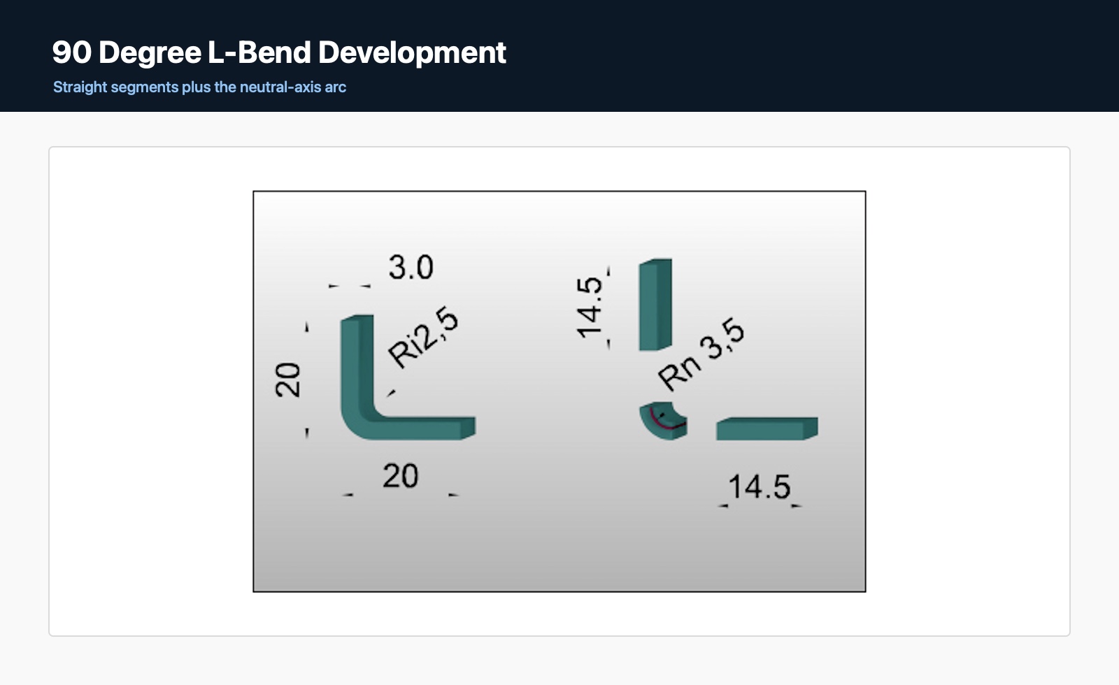

Assume an S235 steel L-section with two 20 mm outside legs, 3 mm thickness and a V20 die. Using the chapter's practical air-bending estimate gives an inside radius of 20 / 8 = 2.5 mm. With K approximately one third, the neutral-axis radius is:
Rn = R + K x T = 2.5 + (1/3 x 3) = 3.5 mm
Each undeformed straight section runs from the flange end to the bend tangent:
20 - 3 - 2.5 = 14.5 mm
The 90-degree bend allowance is one quarter of a circle measured at the neutral radius:
BA = (pi / 2) x 3.5 = 5.50 mm
The developed blank is therefore:
14.5 + 5.5 + 14.5 = 34.5 mm
The outside-dimension route reaches the same result. For a 90-degree bend, OSSB = R + T = 5.5 mm and BD = 2 x 5.5 - 5.5 = 5.5 mm. Flat length = 20 + 20 - 5.5 = 34.5 mm.
Worked example 2: a multi-bend profile
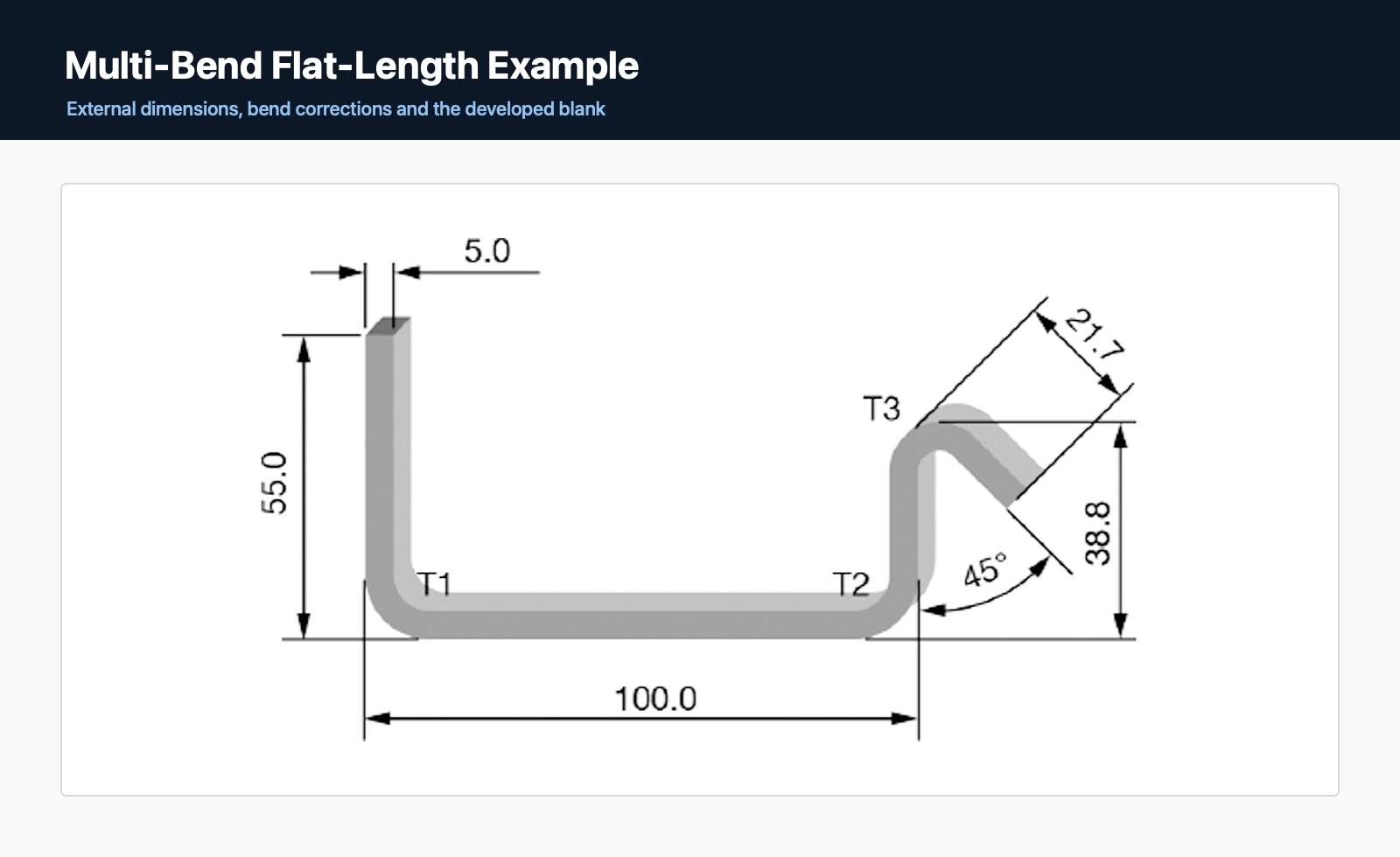
The illustrated S235 profile uses a 5 mm sheet and a V32 die in air bending. The chapter example uses an inside radius of 4.4 mm and calculates three external-dimension corrections: T1 = -9.54 mm, T2 = -9.54 mm and T3 = -4.9 mm. Applying those corrections to the stated outside dimensions gives:
55 - 9.54 + 100 - 9.54 + 38.8 - 4.9 + 21.7 = 191.52 mm
This example highlights an important production rule: every bend owns a local correction. Do not apply one generic deduction to a part that mixes different angles, radii or tool contacts. Calculate each bend, preserve its sign and add the dimensions algebraically.
Four reliable ways to determine flat length
- Controlled bend tests: bend representative coupons and store the measured allowance or deduction by material, thickness, tool combination and machine. This produces highly useful shop data for repeat work.
- CAD/CAM development: unfold the 3D part using a bend table matched to production. Software is fast, but its default K-factor cannot replace a validated process value.
- Geometric calculation: decompose the part into straight tangent lengths and neutral-axis arcs, as in the L-bend example. This method makes every assumption visible.
- Documented bend tables: use an approved internal table or an applicable standard reference, then verify that its radius, thickness, material and angle conventions match the job.
The strongest workflow combines these methods. Use geometry or software for the first development, make a controlled test bend, then update the bend table from the measured result. A validated value is more useful than a formula copied without its process conditions.
Common causes of incorrect flat patterns
- Mixing inside and outside dimensions: this counts or omits the setback around the theoretical apex.
- Using the wrong angle convention: a 45-degree included angle and a 135-degree bend movement can describe the same geometry, but they cannot be inserted into the same formula without conversion.
- Assuming V/8 is exact: the actual inside radius may change with material strength, thickness, tooling and process.
- Treating K-factor as permanent: a value calibrated for one radius or method may not transfer to another.
- Ignoring actual thickness: coil and sheet tolerances can alter radius, force, springback and the developed length.
- Changing tooling without updating the bend table: a different V-opening or punch nose can change the formed radius and invalidate the old deduction.
- Correcting several variables at once: simultaneous backgauge, depth and flat-pattern changes hide the real source of error.
Production validation workflow
- Record material grade, actual thickness, grain direction, target angle, flange datums and tolerance.
- Identify the exact punch, die opening, machine interface, bend length and bending method.
- Calculate the first blank with one documented angle and dimension convention.
- Bend a representative coupon using the production setup and approved load limits.
- Measure the released angle, inside radius and critical flange dimensions with calibrated equipment.
- Convert the measured result into an effective bend allowance, bend deduction or K-factor.
- Make a second verification part before releasing a batch.
- Store the approved result with the drawing, program and tooling models for the next run.
If the profile includes tight returns, multiple heights or removal interference, the flat pattern is only one part of the engineering review. Check the sequence and clearance with the sheet metal bending sequence guide, and compare non-standard geometry with COVO forming tools.
Frequently asked questions
What is sheet metal flat length?
Sheet metal flat length is the cut length of a part before bending. It equals the undeformed straight sections plus the developed length of every bend measured along the neutral axis.
What is the basic bend allowance formula?
Using a bend angle in degrees, bend allowance is BA = (pi / 180) x angle x (inside radius + K-factor x thickness). The angle convention must remain consistent throughout the drawing and calculation.
What is bend deduction?
Bend deduction is the amount subtracted from the sum of outside flange dimensions to obtain flat length. For one bend, BD = 2 x outside setback - bend allowance.
Why is adding the two flange dimensions inaccurate?
The bend occupies a curved zone with a finite inside radius, and material inside that zone is compressed while material outside is stretched. Adding flange dimensions without a bend correction ignores that developed arc.
Can V-opening divided by eight estimate the inside radius?
V/8 is a useful workshop starting estimate for some conventional air-bending conditions. The actual radius also depends on material, strength, thickness, punch nose, die geometry and bending method, so it should be measured on a test bend.
Is K-factor a fixed material property?
No. K-factor is an effective process value that describes the neutral-axis position for a defined bend. It can change with radius-to-thickness ratio, material condition, tooling and bending method.
How should a shop validate a flat-length calculation?
Use production material and the intended punch and die to bend a measured coupon, inspect the released angle, radius and flange dimensions, then update the stored bend allowance or deduction from the measured result.
Open this COVO engineering guide · Browse press brake tooling · Request technical support