COVO KNOWLEDGE
Six-Bend Hat Channel Die: One-Stroke Forming and Release
Published:
Updated:
See how a six-bend hat channel die combines a chamfered punch, matched cavity and spring pad. Review profile geometry, forming load and part release.
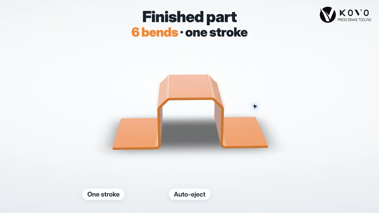
A six-bend hat channel die forms a hat-shaped section with inclined upper shoulders, upright walls and outward flanges in one press brake stroke. COVO's video shows how a profiled punch, matched cavity, flattening shoulders and spring-supported center pad work together around that section. The practical selection question is how those surfaces control the six transitions while supporting and releasing the sheet. Start with the finished section, then review the contact sequence, machine envelope and first-part requirements as one application.
What the six-bend hat channel die forms
A six-bend hat channel die is a matched upper-and-lower forming assembly for a hat section containing six bend transitions. In the illustrated profile, seven faces make up the section: one center web, two inclined shoulders, two upright walls and two outward flanges. The complete section is developed during one closing stroke.
The extra shoulder faces distinguish this application from a simpler hat profile. Dimension their lengths and angles separately from the wall depth and web width. Those features determine the working contour; describing the part only as a “hat channel” leaves important geometry unresolved.
Compare six-bend and four-bend hat sections
| Drawing feature | Four-bend hat section | Illustrated six-bend section |
|---|---|---|
| Web-to-wall connection | One bend on each side. | An inclined shoulder adds a second transition on each side. |
| Planar faces across the section | Web, two walls and two flanges. | Web, two shoulders, two walls and two flanges. |
| Profile review | Web width, wall depth, flange dimensions and four radii. | Additional shoulder lengths, angle references and two more radii. |
| Tooling decision | Match the required four-corner section. | Review the added contacts, support and release of the shoulder profile. |
The four-bend hat-channel forming guide covers the simpler section and its production example. A tool for that profile cannot be selected from bend count alone for the shoulder-equipped part shown here.
How the punch, cavity and spring pad work together
The video identifies a chamfered punch nose and flattening shoulders. The nose provides the inside working contour around the upper part of the section. The shoulders act on the outward flange regions, while the lower cavity accommodates the outside profile. Their relative positions establish the combined contact geometry.
The spring pad sits in the center of the lower cavity beneath the web. It provides a movable bearing face as the section develops and returns upward to assist release when the punch retracts. Review its guidance, travel and force together with the fixed tool surfaces. Support during closure and release after forming are separate design checks.
The intended sequence must allow material to move into the cavity without a flange locking too early or pulling the section off center. One closing movement can contain several stages of contact. Confirm the loading datum, support arrangement and extraction direction from the actual assembly drawing.
Read the 45° tool label and surface description correctly
The video's 45° label belongs to the chamfered nose. Specify the required released shoulder angle separately, with its datum and tolerance. WILA's tool-angle explanation describes why tooling geometry, the forming method and springback must be considered together. Inspect the unloaded section rather than accepting the tool label as a finished-angle measurement.
The animation also describes hardened tool steel and a precision-ground, mirror finish. For an enquiry, translate that description into an agreed tool specification and acceptable part-surface sample. Visible polish alone establishes neither a roughness value nor a mark-free forming result.
Six checks before selecting the tooling
- Define the complete section. Supply web width, shoulder lengths, wall depth, flange widths, angles and radii. Mark datums and tolerances; include the full part and nearby features.
- Identify the production stock. Record material grade, condition, thickness range, coating and cosmetic faces. Agree which representative stock will be used for the first-part trial.
- Confirm blank location and support. Show the locating edge, blank preparation and support throughout closure. Check how any existing bends affect gauging and access.
- Review the pad and contact sequence. Confirm the spring-pad arrangement, guidance, travel and load contribution. Establish when the web, shoulders, walls and flanges contact their working surfaces.
- Check machine fit and forming load. Provide the clamp interfaces, installed height, open height, stroke and loaded length. Obtain approval for the complete tool-and-machine combination.
- Plan release and inspection. Review the opening and extraction path. Agree on measurements, surface acceptance and the first-part record before production release.
WILA's load-capacity guidance identifies tools, holders and the press brake as separate possible limits. For this matched forming assembly, request a process-specific force review rather than multiplying an ordinary single-bend estimate by six.
Inspect the released section before approving the batch
Measure web width and depth, both shoulders, wall spacing, flange widths and flatness at the drawing datums. Compare both sides for symmetry, then inspect straightness, twist, corner cracking and contact marks along the working length. Record results after the part has unloaded.
If a flange bows or one shoulder differs from the other, review seating, alignment, stock and contact sequence before increasing force. Confirm that the pad returns and the part leaves the tools by the planned route. Follow the machine and tooling supplier's handling and safeguarding procedure.
FAQ
What makes this a six-bend hat channel?
The illustrated section has a center web, two inclined shoulders, two upright walls and two outward flanges. Six transitions connect those seven faces. A conventional four-bend hat section connects its web directly to the walls. Show every face, radius and angle on the drawing so the supplier can identify the intended profile.
Do all six bends form at exactly the same instant?
One stroke describes one closing movement of the matched tool set. Contact can develop progressively as the sheet meets the nose, shoulders and cavity. The approved design must establish that sequence, including sheet support and material movement. The number of finished bend lines does not establish simultaneous contact or equal loading at every corner.
Does the 45° chamfer specify the finished shoulder angle?
The video labels the tool's chamfered nose as 45°. The finished shoulder angle needs its own drawing reference and tolerance, measured after unloading. Tool geometry, contact and material springback must be reviewed together. Specify whether the angle is measured from the web, the wall or another datum rather than transferring the tool label directly to inspection.
What does the spring pad do in the illustrated die?
The center pad provides a movable support beneath the channel web. Its spring-supported return assists release as the tools open. The application design must define pad travel, guidance and force in relation to the forming stroke. A visible spring mechanism alone does not establish flange flatness, reliable ejection or the allowable material range.
Can a six-bend hat channel die form different materials?
Use only the material and thickness combinations approved for the selected assembly. A change of grade, condition, coating or thickness can affect springback, contact, required load and visible finish. Provide the intended range at quotation and agree on representative first-part trials. Reusing the same external profile does not automatically qualify a different stock.
How should the forming force be established?
Request a load review for the complete contact sequence, material, thickness and loaded length, including the pad's contribution. Counting six bend lines is insufficient to calculate the force. Compare the resulting requirements with the punch, die, holders and press brake ratings, and document the permitted setup before a controlled first-part trial.
Request a COVO section review
COVO Precision Tooling is the tooling brand of Nanjing Kovo Intelligent Equipment Co., Ltd., based in Nanjing, China. It manufactures standard and custom press brake punches and dies. Explore the forming-tool family, then request a six-bend hat channel die recommendation with the dimensioned section, full part model, material specification, quantity, loaded length, surface requirements and machine details. Identify the shoulder geometry and inspection datums explicitly.
Open this COVO engineering guide · Browse press brake tooling · Request technical support