COVO KNOWLEDGE
One-Stroke Hat Channel Forming Tool: Four Bends in One Cycle
Published:
Last reviewed:
See how a custom press brake hat-channel tool forms four bend lines in one stroke, where it works best and what data COVO needs to design it.
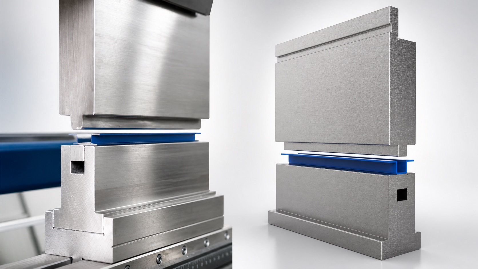
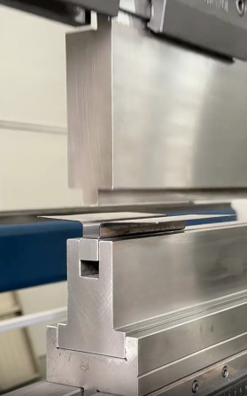
A one-stroke hat channel forming tool creates a shallow channel or stiffening profile with four bend lines in one press brake cycle. The blank is located once, a broad upper forming block drives it into a matched lower cavity, and the tool controls the center web, two side walls and two outward flanges as one connected section.
The COVO tool shown in the supplied production footage is a dedicated forming set rather than a conventional punch and V-die. Its purpose is not to replace standard air bending for every job. It is designed for a repeat profile where multiple separate bends would add handling, datum changes, accumulated error or clearance problems.
What profile does this special press brake tool form?
A hat channel has a center web, two approximately parallel walls and two flanges extending away from the channel. Its section resembles a shallow top hat when viewed from the end. Depending on orientation, the same geometry may also be described as a formed stiffener, mounting channel, rail or recessed reinforcement.
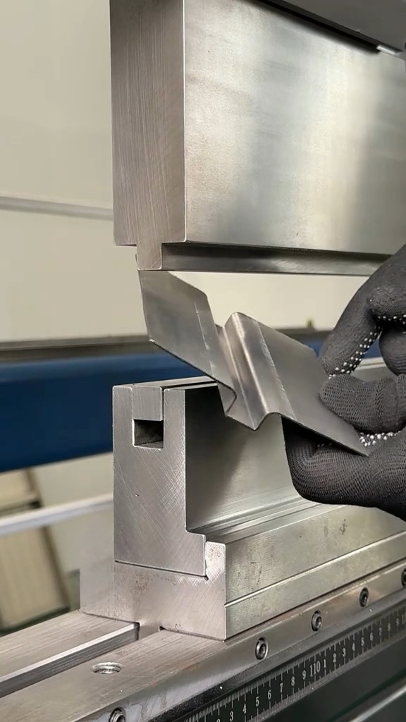
The profile in the COVO footage is formed from a flat blank. Instead of creating each corner with a separate standard bend, the matched tool develops the complete section during one closing movement. The result is especially relevant when the distance between the two walls, the web width and the relationship between both flanges must remain consistent.
Structural analysis of the tooling
Wide upper body with a defined working projection
The upper tool uses a wide, rigid body instead of a slender general-purpose punch. Near its working edge, the geometry narrows into the forming region that enters the lower tool. This construction provides support behind the active profile and gives the designer enough material to manage strength, deflection and the machine interface.
Matched lower cavity and support lands
The lower tool is not an open V-die. Its upper lands support the blank before the stroke, while the recessed internal area receives the developing channel. The side relief visible in the production image confirms that the die body includes internal clearance around the forming region. A released design may use fixed, spring-supported or replaceable elements, but that detail cannot be determined reliably from an external photograph alone.
Clearance for the finished channel
As the upper tool descends, the center of the blank must move into the lower cavity without trapping the newly formed walls. The tool therefore needs sufficient cavity depth, corner relief and stripping clearance. The removal path is as important as the closing path: a correct profile that cannot be released safely is not a production-ready tool.
A shared force path across four bend zones
Four bends are created as one connected forming event. Contact does not necessarily occur everywhere at the same instant; it develops as the sheet meets the shoulders, rotates into the cavity and approaches the calibrated bottom position. The designer must control that sequence so one corner does not lock prematurely or pull the profile off center.
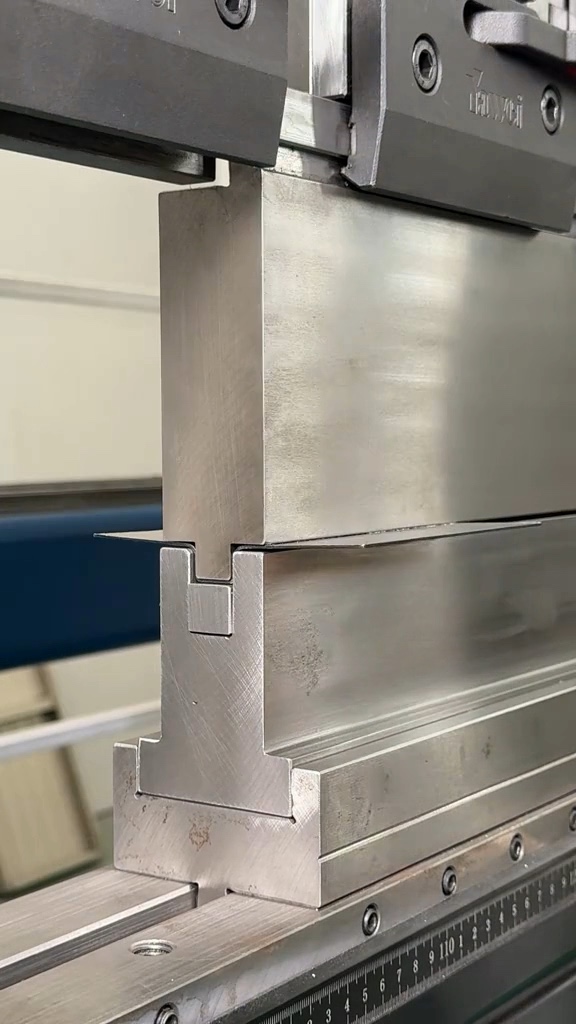
How the one-stroke forming cycle works
- Locate the blank: the flat or pre-qualified blank is positioned against the approved gauge or nesting reference. Both outer flanges need stable support.
- Establish first contact: the upper working region contacts the sheet while the lower lands keep the blank centered and level.
- Develop the side walls: continued travel draws the center region into the cavity and rotates material through the four designed bend zones.
- Calibrate at the working depth: the final portion of the stroke establishes the web depth, wall spacing and released-angle compensation defined for the material.
- Retract and strip: the ram rises, the workpiece releases from the tool and the operator removes the completed channel for inspection.
Why combine four bends in one press brake stroke?
The strongest production advantage is not simply a shorter ram cycle. It is the removal of repeated locating steps. A conventional route may require the operator to form one wall, rotate or reposition the blank, establish a new datum and then repeat the process for the opposite side. Every relocation can change the center distance, flange length or symmetry.
- One locating event: the blank is referenced once for the connected profile.
- Better sectional consistency: both walls and both flanges are controlled by the same matched tool relationship.
- Less handling: fewer rotations and gauge changes can reduce cycle time and operator effort on repeat batches.
- Lower accumulated error: four bend zones are not built from four independent positioning decisions.
- Clearer first-article approval: web depth, wall spacing, flange width and overall symmetry can be inspected as one finished feature.
These benefits depend on a stable blank, material and approved setup. A dedicated tool does not eliminate springback, thickness variation, machine deflection or tooling wear; it concentrates them into a process that can be measured and documented more consistently.
Typical applications for hat channels and formed stiffeners
Hat-shaped channels are useful where a thin sheet needs local stiffness, a repeat mounting feature or a controlled recessed rail. A custom one-stroke tool may be considered for:
- Electrical enclosures, cabinet doors and equipment panels.
- Machine guards, covers and structural sheet-metal skins.
- HVAC housings, duct components and service panels.
- Vehicle, trailer and rail interior components.
- Shelving, racks, brackets and mounting rails.
- Appliance panels and fabricated frames.
- Repeat channels that would otherwise require several separate press brake setups.
The tool should be chosen because the required section and production quantity justify it, not because every shallow channel needs special tooling. Standard punches and dies remain more flexible for prototypes, changing dimensions and low-volume parts.
Critical design inputs
A hat-channel tool is a matched forming system. COVO needs the following information before the working geometry and load can be approved:
- Finished section: web width, wall depth, flange widths, inside radii, included angles and dimensional tolerances.
- Material: grade, thickness, tensile or yield-strength range, temper, grain direction and surface condition.
- Working length: total formed length, segmentation requirements and any interrupted features.
- Press brake: make, model, tonnage, working length, stroke, open height, clamping system and crowning method.
- Production target: batch size, annual quantity, changeover goal and inspection frequency.
- Part handling: blank datum, backgauge access, support method, stripping direction and available removal clearance.
- Appearance: visible faces, coating, stainless finish or requirements for low-mark contact.
The generic COVO Bending Force Calculator is useful for comparing ordinary air-bending conditions, but a four-zone matched forming tool requires an application-specific load review. The upper tool, lower die, holders and press brake must all remain within their approved load limits.
Springback, calibration and first-piece inspection
At the bottom of the stroke, the tool geometry is designed around the expected released profile, not merely the nominal CAD section. Material strength and thickness influence how far the walls recover after unloading. A verified tool may therefore include controlled over-form, radius compensation or a calibrated shut position.
Inspect the first production part at minimum for web depth, distance between walls, flange width, wall angle, overall symmetry, twist and surface marking. Measure after the part has fully released. Store the approved ram correction, material lot, tool identity and gauge position with the job so the next run begins from evidence rather than memory. The COVO springback and K-factor guide explains why the released geometry can differ from the loaded shape.
When this tooling is a strong fit
- The same channel profile is produced repeatedly.
- Four separate bends create too much handling or dimensional accumulation.
- Wall spacing and flange symmetry are critical acceptance features.
- The part can be located and removed safely from a matched cavity.
- The production saving justifies a dedicated upper-and-lower tool set.
When another process may be better
- The section dimensions change frequently or the job remains at prototype volume.
- The material range is wider than the qualified tool clearance and load window.
- The part contains adjacent features that collide with the tool body.
- The required channel cannot be stripped after forming.
- A roll-forming, stamping, panel-bending or multi-stage route is more economical for the quantity and geometry.
COVO's custom tooling workflow
- Application review: COVO studies the drawing, sample, material, machine interface and current production problem.
- Forming concept: the team defines contact sequence, cavity geometry, working height, load path and removal direction.
- Design verification: 3D review and motion analysis are used to identify interference, unsupported sheet movement and stripping risks before manufacture.
- Approval drawing: the customer confirms the finished profile, machine interface and critical dimensions.
- Manufacture and inspection: the tool is machined, heat-treated where specified, finished and checked against the released design.
- Production validation: the first-part plan records material, machine settings, measurements and any approved correction.
For broader design context, see How COVO Designs Special Forming Tools, compare a different one-stroke profile in the Z-bending tool guide, or browse COVO's forming tools.
Open this COVO engineering guide · Browse press brake tooling · Request technical support