COVO KNOWLEDGE
Z-Bending Tool Holders and Changeable Inserts: Setup Guide
Published:
Updated:
Explore Z-bending tool holders and changeable inserts with COVO's video. Learn selection checks, insert changeover and long-flange clearance.
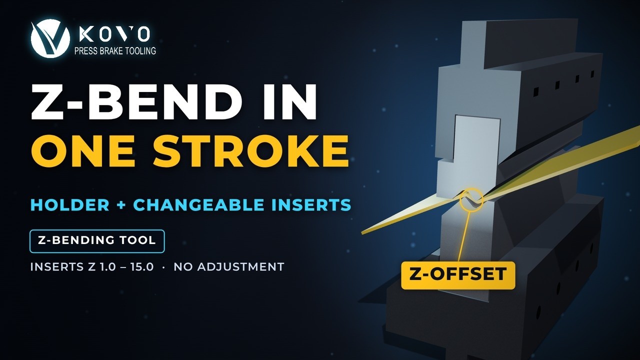
A modular Z-bending tool combines a holder with a matched pair of changeable inserts to form the two bends of an offset feature in one press brake stroke. Z-bending tool holders provide the mounting arrangement; the selected inserts provide the working profile. The COVO video below illustrates this construction, shows how chamfered holders give long flanges room to move, and presents a 10 mm offset in 2.0 mm sheet as an example. This guide explains what to specify when selecting or changing inserts and what to verify before releasing the setup.
How Z-bending tool holders work with changeable inserts
The assembly separates the mounting function from the forming geometry. Upper and lower holders retain the working inserts. As the press brake closes, the complementary profiles bend the sheet in opposite directions to create the step. Replacing the approved insert pair makes another profile available while retaining compatible holders.
This modular principle also appears in WILA's offset-bending explanation and the UKB Z-tool holder and insert family. Their specifications apply to their own products. They do not establish interchangeability or load ratings for the COVO assembly.
For the broader choice between custom offset geometries, read the one-stroke Z-bending tools guide. Here the focus is choosing a compatible insert and managing a repeatable changeover.
Read the COVO video: mechanism, clearance and example
- Two bends belong to one offset feature. The animation shows the insert peak and valley forming the two 90° bends together. This describes the illustrated feature; a finished part with other flanges may still require additional operations.
- The holder remains part of the assembly. The video introduces a holder with changeable Z-inserts labelled Z 1.0–15.0. Treat those as the demonstrated series labels and obtain the selected insert drawing. Do not read the range as allowable sheet thickness or assume that a nominal label defines every finished dimension.
- Chamfers provide room for flange movement. The 45° relief on the holders gives the illustrated long flange space to swing during closure. Check that motion against the actual workpiece and the complete installed tool stack.
- The dimensions describe one example. The source states a Z-offset of 10 mm (0.394 in) and sheet thickness of 2.0 mm (0.079 in). It provides no material grade, loaded length, measured accuracy or forming-force record. Use those values to follow the animation, then specify your own application.
The video's “no adjustment” wording refers to the demonstrated holder-and-insert arrangement. An insert change still requires the prescribed installation and setup checks. The animation does not measure a changeover time or prove a percentage reduction in cost or cycle time.
Six decisions before selecting a modular Z-bending tool
- Define the released section. Supply the offset datum, both finished angles, radii, flange lengths and tolerances. Identify whether the offset is measured between outside faces, inside faces or another drawing reference. Keep the finished-section requirement separate from the insert's catalogue designation.
- Match the inserts to the holders. Confirm the upper and lower insert identities, seating geometry, retention method and usable working length. Review the holder and machine clamping interfaces together. Similar-looking inserts are not evidence of a matched assembly.
- Identify the actual sheet. Record grade, condition, thickness range, bend length, coating and protective film. Mark any cosmetic face. Material variation and springback need an application review; the rendered result cannot approve a different stock or finish.
- Check installed height and the complete motion. Include holders, inserts, adapters and clamps when reviewing open height, ram stroke, workpiece loading and removal. Check nearby returns and the backgauge as the flange moves. A clear cross-section at closure alone does not establish a clear handling path.
- Obtain process-specific load approval. Confirm forming force for the intended material, profile and loaded length against the inserts, holders, retention components and press brake. Include lateral-force requirements where relevant. A conventional air-bending tonnage estimate does not approve a dedicated offset assembly.
- Agree on first-part acceptance. Specify how the released offset, angles, straightness and surface will be inspected. Record the approved assembly and controller program. Accept the first representative part before using the combination for the batch.
The COVO offset calculator can support an initial geometry discussion. It does not validate holder compatibility, forming force or the collision envelope of a modular Z-bending tool.
Compare insert changes with other tooling arrangements
Choose by the required profiles and the available machine access. The table compares setup structure; it makes no claim about measured speed or cost.
| Arrangement | What changes | Useful application question | Evidence required |
|---|---|---|---|
| Compatible holder with changeable Z-inserts | The approved working insert pair changes; compatible holders can remain. | Can a reviewed holder family support the required group of offset profiles? | Matched interfaces, insert drawings, load approval and first-part results for each combination. |
| Complete fixed-profile offset set | The full upper and lower working set changes when another profile is required. | Does a dedicated profile suit a repeat job or a special section? | Complete set geometry, clamping compatibility, force and part clearance. |
| Two separate bends with conventional tools | The workpiece is positioned for each bend in the selected sequence. | Can the second bend be reached and supported after the first? | Sequence review, bend spacing, handling clearance and finished-section inspection. |
Plan the insert change and inspect the first part
Use the machine and tooling supplier's approved handling, isolation and clamping procedure. Confirm the insert identities and inspect the seating and retention surfaces before assembly. Follow the specified tightening and alignment instructions; do not infer a universal torque or loading method from the animation.
After installing the matched pair, confirm the program, material and approved load. Inspect the first released section at the drawing datums. If the offset is incorrect, check the selected profile and material before changing ram depth. If angles vary along the part, review seating, alignment and machine setup. Investigate twist, contact marks or difficult removal before continuing.
Sectionalized Z-tools are mentioned as available on request in the video description. Specify the needed segment arrangement and part access when requesting them. Segmenting a tool does not by itself resolve an obstruction or establish the allowed load for the assembled working length.
Request a COVO holder-and-insert review
COVO Precision Tooling is the tooling brand of Nanjing Kovo Intelligent Equipment Co., Ltd., based in Nanjing, China. It manufactures standard and custom press brake punches and dies. For a modular offset application, begin with the COVO Z-bending tools family and confirm the interface for your actual machine.
Request a tooling recommendation with the machine model and clamp details, material grade and thickness range, loaded length, dimensioned finished section, required quantity and surface requirement. Add existing holder drawings or identification if you want to reuse holders, plus the complete part model for clearance review.
FAQ
Can one Z-bending holder accept every offset insert?
No. Use the insert pair approved for the holder's seating geometry, retention system, working length and load rating. A similar outline or the same nominal Z dimension does not establish compatibility across tool families or manufacturers. Confirm the complete assembly from its drawing and identification before installation.
Can ram depth replace changing the Z-bending insert?
Select the insert geometry for the required finished offset and angles. Ram depth remains a controlled process setting, but it does not turn a fixed insert profile into a tool for arbitrary offsets. Review any proposed setting change against the approved process and inspect the released section.
Does no adjustment mean no setup checks are required?
The video uses this phrase for its illustrated holder-and-insert arrangement. It does not remove checks for seating, retention, alignment, installed height, controller settings, approved load and first-part dimensions. Follow the tool and machine instructions whenever inserts are exchanged.
Do the Z 1.0–15.0 labels describe sheet thickness?
The supplied video presents Z 1.0–15.0 as its Z-insert series labels, not a sheet-thickness capacity range. Its example separately states a 10 mm (0.394 in) Z-offset and 2.0 mm (0.079 in) sheet thickness. Confirm the actual insert dimensions, material and thickness capability from the selected tool drawing and application data.
Do 45° holder chamfers guarantee clearance for long flanges?
The chamfers provide space for the flange movement illustrated in the animation. The actual part still needs clearance from the upper and lower tools, clamps, holders, machine and backgauge throughout forming and removal. Review the complete part envelope, including existing returns and supports.
What should be inspected after replacing Z-bending inserts?
Confirm the matched assembly, clean seating, alignment, retention, material, program and approved force. Inspect a representative released part for offset height, both angles, radii, straightness, twist and surface condition. Record the accepted combination and settings before starting the production batch.
Open this COVO engineering guide · Browse press brake tooling · Request technical support