COVO KNOWLEDGE
How to Use a Press Brake Bending Rule: V-Opening, Minimum Flange, Radius and Tonnage
Published:
Last reviewed:
Use a press brake bending rule to select V-opening, check minimum flange and radius, estimate tonnage and validate a safe production setup.
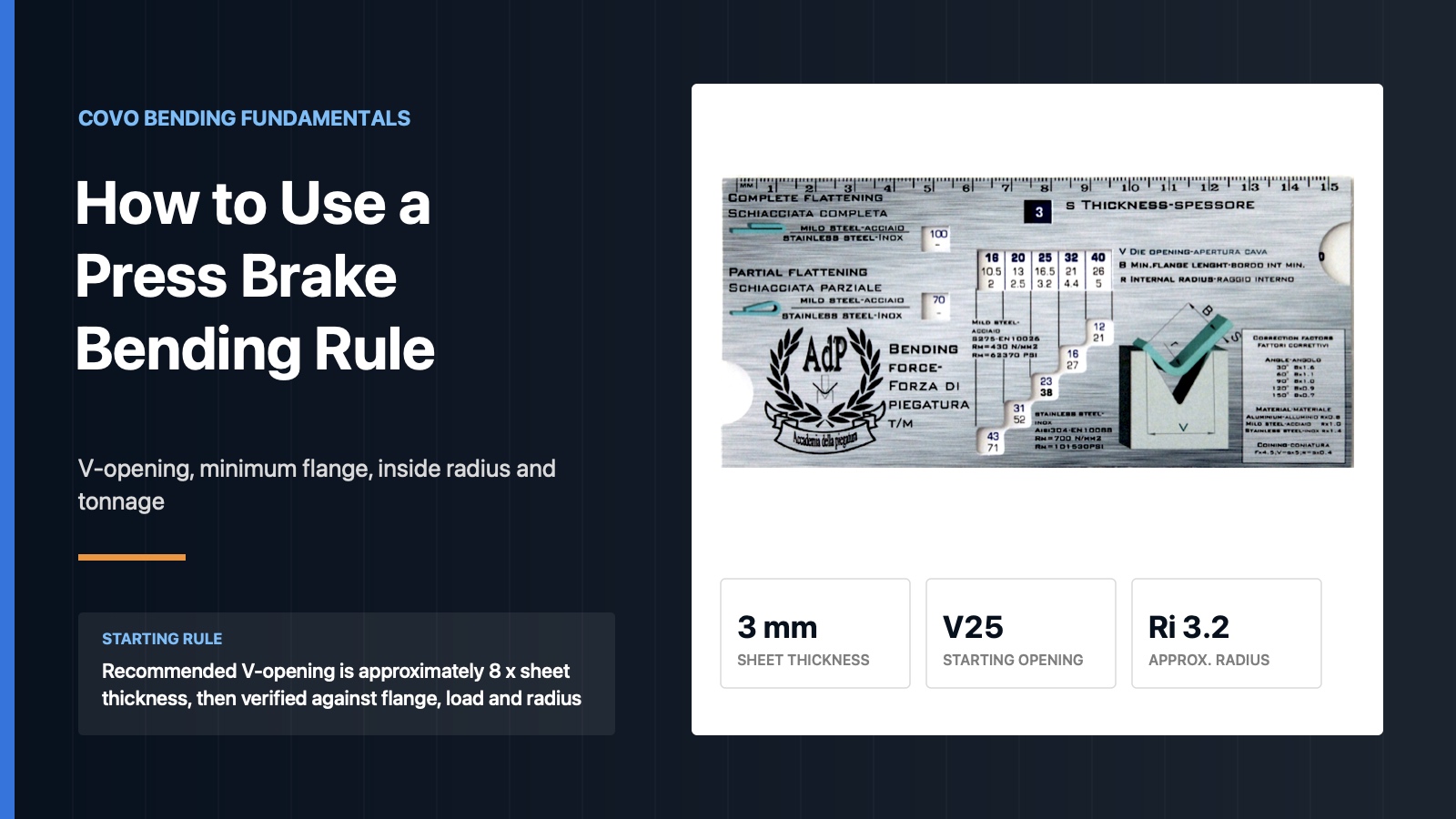
A press brake bending rule is a compact feasibility tool that links sheet thickness to usable V-die openings, minimum flange length, approximate inside radius and bending force. It helps designers and operators reject an impossible setup before a blank is cut, but it does not replace the load ratings, machine data, collision review or first-piece test required for production.


Why use a bending rule before production?
CAD and offline programming can create a convincing flat pattern without proving that the available press brake and tooling can make it. The most common gap is not drawing speed; it is manufacturing context. A flange can be too short to sit on both die shoulders, the required force can exceed a tool rating, or the selected opening can produce a radius that no longer matches the drawing.
A bending rule gives the technical office a fast first filter. It brings four linked questions into one view: which V-opening is plausible, how much flange support it needs, which radius range it is likely to form, and how much force the bend may require. When those values are checked before nesting and cutting, the shop avoids preventable redesign, scrap and unsafe trial setups.
The rule is especially useful when a drawing reaches the workshop with only nominal thickness and angle. It prompts the team to add the missing process data: actual material, bend length, tool interface, available punch and die profiles, press capacity, visible-surface requirement and the inspection method for the first article.
What do S, V, B, Ri and t/m mean?
| Symbol | Meaning | How to use it |
|---|---|---|
| S | Actual sheet thickness in millimetres | Use the measured or controlled production thickness, not only the nominal drawing value. |
| V | V-die opening | Compare several available openings around the starting ratio and check their load rating and shoulder geometry. |
| B | Minimum supported flange | Verify that the blank rests securely on both die shoulders at the beginning of the stroke. |
| Ri | Approximate inside bend radius | Use it for planning, then measure the released first bend because the real radius is not a perfect circular arc. |
| t/m | Estimated tonnes per metre | Multiply by actual loaded bend length and compare with machine and tooling limits, including concentrated-load limits. |
| Correction factor | Adjustment for angle, material or bending method | Apply only the factor that belongs to the same rule, units and process assumptions. |
How to use a press brake bending rule step by step
- Confirm the material and actual thickness. Record grade, strength range, thickness, grain direction, surface condition and bend length. These values influence force, springback, radius and marking.
- Set the thickness on the rule. Align the sliding scale with S. The available columns now show a family of candidate V-openings rather than one compulsory die.
- Start near V = 8S. The centre column in the referenced rule is approximately eight times thickness and represents a balanced air-bending starting point.
- Check the minimum flange B. Compare the displayed support length with the straight material available from the bend line to the blank edge. Use the tool supplier's current minimum-flange guidance when it is more conservative.
- Read the approximate inside radius Ri. Compare the result with the drawing, flat-pattern assumptions and punch nose. Treat it as a process estimate, not a guaranteed finished dimension.
- Read or calculate the force. Select the material line, convert the value to the actual bend length, and include any approved angle or method factor.
- Check every load limit. The safe value is controlled by the weakest relevant component: press brake, punch, die, holder, adapter or short loaded segment.
- Check physical feasibility. Confirm open height, stroke, tool seating, return-flange clearance, backgauge access, part support and removal path.
- Run and measure a first article. Inspect released angle, inside radius, flange dimensions and visible surfaces, then store the approved correction with the exact tool combination.
For a quick independent estimate, use the COVO Bending Force Calculator. For flange support, compare the selected opening with the minimum flange length calculator. Both are preliminary planning aids and should be reconciled with the approved tooling data.
Worked example 1: 2 mm sheet with a V16 starting die
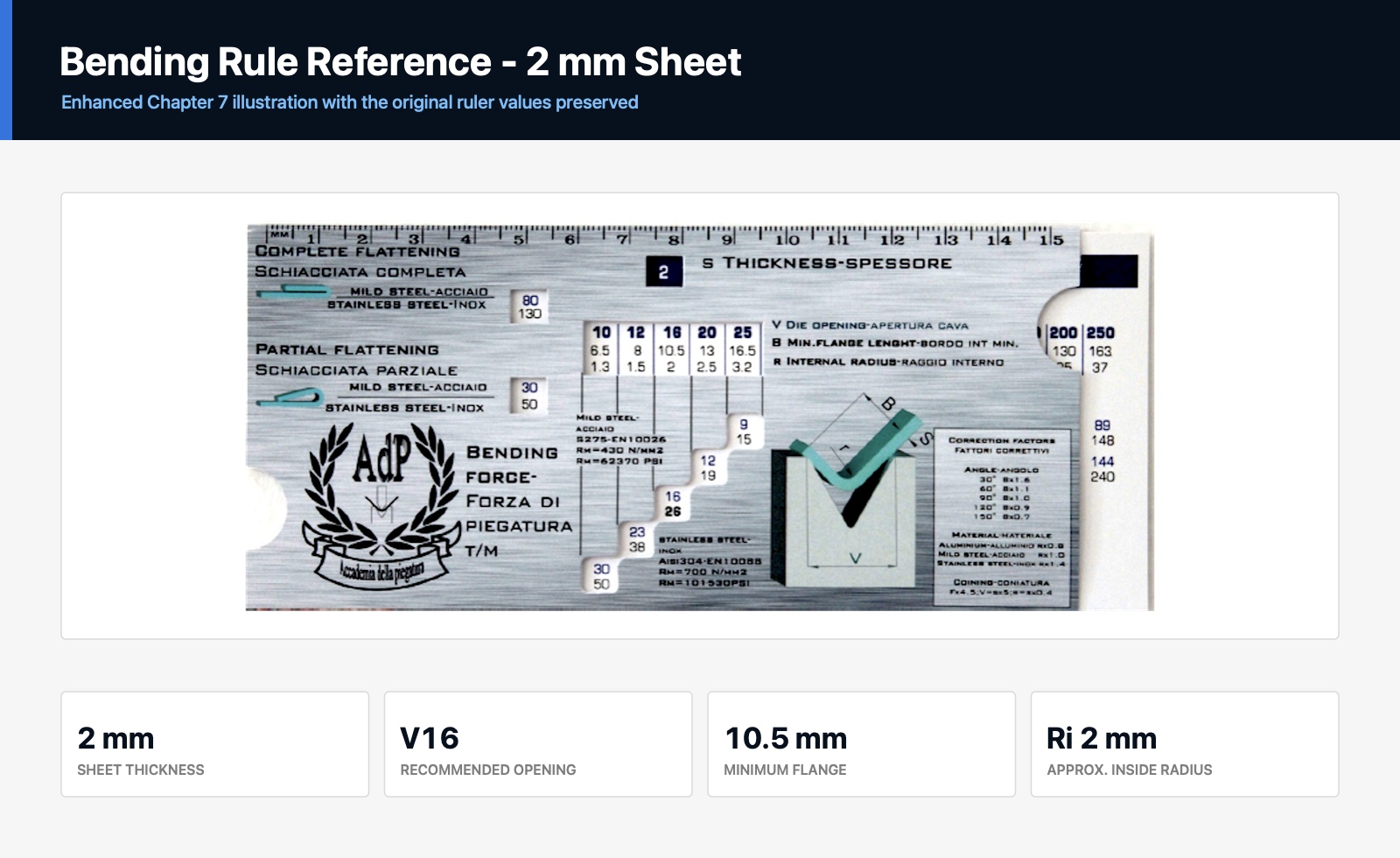
For S = 2 mm, the central opening follows the starting relationship 2 x 8 = 16 mm. The referenced rule associates that opening with B = 10.5 mm and Ri = 2 mm. Those three values must remain linked: selecting a different opening changes both support length and the predicted radius.
The same row also shows smaller and larger openings. A narrower V10 or V12 can help when the flange is short or a smaller formed radius is required, but the load and contact pressure rise. A wider V20 or V25 reduces the preliminary air-bending force but needs more flange support and forms a larger radius. The correct choice is the opening that satisfies geometry, force, surface and tool-rating requirements together.
Why V = 8S is a starting point, not a law
| Opening choice | Typical effect | Engineering check |
|---|---|---|
| Narrower than 8S | Shorter minimum flange and smaller approximate radius, with higher force and higher local contact pressure. | Tool strength, machine tonnage, marking risk, bend angle and punch-to-die compatibility. |
| Near 8S | Balanced starting condition for many conventional air-bending jobs. | Actual material strength, available commercial opening and first-piece radius. |
| Wider than 8S | Lower preliminary force, with a longer minimum flange and larger approximate radius. | Drawing radius, springback, flange support, machine daylight and part clearance. |
The ratio can move outside this range for high-strength steel, aluminium, large-radius work, short flanges, visible panels, bottoming, coining or special forming. Do not force the job into an 8S opening when another requirement controls the process. Compare standard COVO press brake dies, compatible punch profiles and dedicated forming tools before changing the drawing around a single available die.
The displayed inside radius is an approximation
A released air bend rarely forms a mathematically perfect circular arc. Contact near the die shoulders and punch nose can produce a curve with different local radii, and thicker sheet may show slight changes close to the punch-tip impression. Material strength, anisotropy, actual thickness and springback add more variation.
Use the ruler radius to screen the drawing and choose a sensible punch nose, then measure the first bend. The chapter's 2 mm mild-steel example treats punch nose radii of 0.8, 1.2 or 1.5 mm as plausible candidates around the theoretical 2 mm formed radius, while a 3 mm punch radius is not the preferred starting choice for that condition. This example is not a universal tooling rule; the real punch must also satisfy its profile, angle, load rating and the required surface quality.
If flat length is critical, connect the measured radius to the COVO flat-length, bend allowance and K-factor guide. Updating the flat pattern from a theoretical radius while leaving the physical process unchanged can move the flange error rather than solve it.
Worked example 2: 3 mm sheet in a V20 die
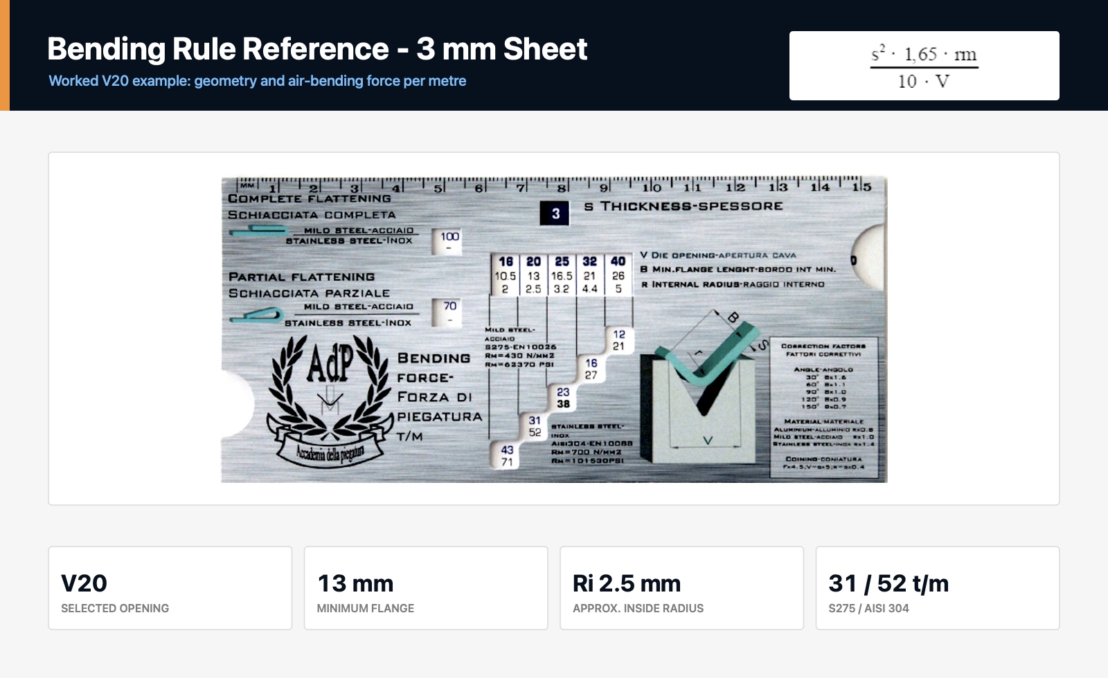
The recommended centre opening for S = 3 mm is the commercial V25 size because 3 x 8 = 24 mm. The chapter then deliberately selects the narrower V20 column to show how the rule is read when geometry requires another available die. That column gives B = 13 mm and Ri = 2.5 mm.
The preliminary air-bending force formula presented in the chapter is:
F (t/m) = 1.65 × Rm × S² / (10 × V)
Here S and V are in millimetres, Rm is tensile strength in N/mm², and F is tonnes per metre. Using the chapter's reference strengths:
- Carbon steel reference: 1.65 x 420 x 3² / (10 x 20) = 31.2 t/m, rounded to 31 t/m on the rule.
- AISI 304 reference: 1.65 x 700 x 3² / (10 x 20) = 52.0 t/m.
- Half-metre loaded bend: the geometric length conversion gives about 15.6 t for the carbon-steel reference or 26 t for the stainless reference before any applicable process correction.
The formula is a planning model, not a machine command. Use the actual certified or controlled strength when available, the real loaded length, the current tool ratings and the press brake manufacturer's calculation convention. Short tooling segments and concentrated loads can reach a local limit even when the total machine tonnage appears adequate.
Material, angle and bending-method corrections
The rule includes correction areas because the central table cannot represent every bend with one value. The minimum supported flange changes as the bend angle changes. Material affects the effective formed radius and springback: stainless steel commonly produces a larger radius than a comparable mild-steel reference, while aluminium can produce a smaller one under the stated rule assumptions.
Correction factors are not portable between every chart, calculator and manufacturer. First identify which base condition the rule uses, then apply only its matching factor. Mixing a force factor from one source with a radius or angle convention from another can create a confident but inconsistent result.
Coining must be treated separately. The chapter uses a planning correction around 4.5 times the air-bending force. That number is a warning about the scale of the load, not permission to coin with a tool selected only from the air-bending table. Confirm the punch and die profile, rated load, machine capacity, local load distribution and the reason coining is required.
Hemming and flattening are separate load cases
The bending rule also presents complete and partial flattening, often used to remove a sharp sheet edge or create a hem. The illustrated guideline limits this reference to a maximum of about 2 mm stainless steel and 3 mm mild steel. Those values belong to the pictured tool and rule; they are not universal press brake limits.
A complete hem closes the adjacent faces, while a partial hem preserves a teardrop-shaped air space. Both operations change contact area during the stroke and can create high local pressure. Verify the dedicated hemming tool, flattening force, material ductility, surface requirement, return geometry and removal path. If the part needs a visible no-mark finish, compare a purpose-built mark-free solution instead of adding an uncontrolled temporary layer.
Tool segmentation is part of feasibility
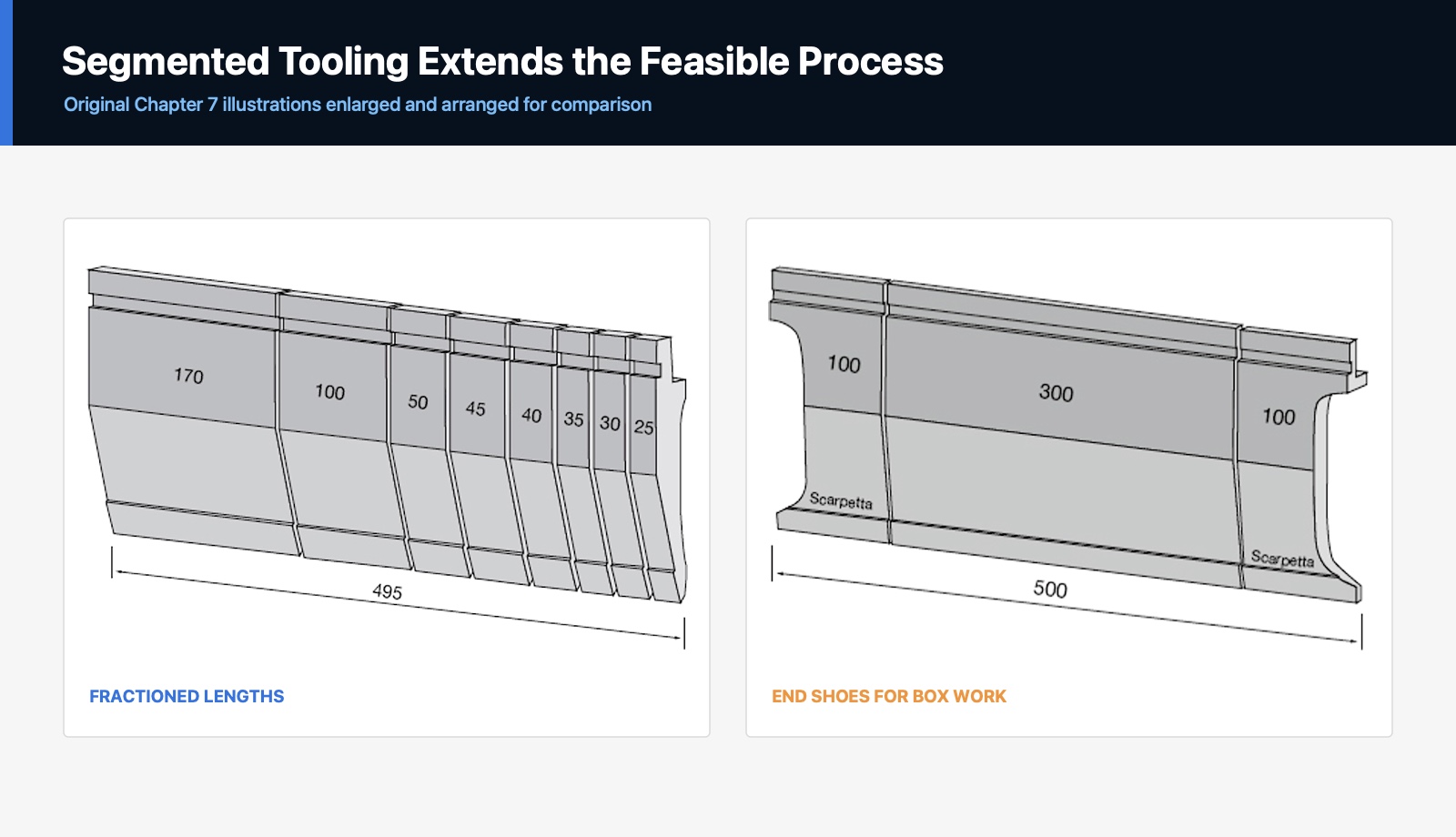
The numerical rule can approve the opening, flange, radius and force while the physical job still fails because the tool length or profile is unavailable. Segmented punches and dies let the operator assemble a required working length and create local gaps for box walls, returns or part withdrawal. The exact segment pattern is manufacturer- and system-specific.
The chapter describes a classic Promecam-style 835 mm set assembled from 10, 15, 20, 40, 50, 100 and 370 mm pieces. Other systems use different segment families. Mirrored end pieces with a relieved shoe can help complete inner bends in box sections. Record the installed order and working length so a future setup reproduces the same support and load distribution.
Browse COVO holders, clamps and tooling accessories when the approved process needs a compatible clamping or storage arrangement. An adapter can solve an interface problem, but it also changes working height, open height and the number of loaded interfaces.
Common bending-rule mistakes
- Using nominal thickness without checking the production sheet: force scales with thickness squared, so a small thickness change can move the estimate noticeably.
- Choosing V = 8S automatically: short flange, target radius, surface quality or material strength may require another opening.
- Reading B as a guaranteed finished flange: it is a support limit for the stated geometry and needs the rule's safety assumptions.
- Treating Ri as exact: the real released bend is material- and tooling-dependent and may not be a regular arc.
- Checking only machine tonnage: the punch, die, holder, adapter or short segment may have the lower rating.
- Multiplying by overall tool length: force must use the actual loaded bend length, while local concentration still needs review.
- Using air-bending values for coining or flattening: these operations have different load paths and tool requirements.
- Ignoring clearance and removal: a numerically valid bend can still collide with the holder, ram, backgauge or finished return.
- Skipping the first article: the rule cannot measure the real angle, radius, flange or surface after springback.
Press brake bending-rule release checklist
- Material grade, actual thickness, tensile-strength range and bend length are recorded.
- Candidate V-opening is compared with minimum flange, target radius and available die geometry.
- Preliminary force is converted to the actual loaded length and checked against every relevant rating.
- Punch nose, included angle, working height, die shoulders and clamping interface are identified.
- Angle, material, coining or hemming factors use one documented calculation convention.
- Return-flange clearance, backgauge access, part support and removal are verified.
- Segment lengths and their installed order are documented for repeat work.
- A controlled first article confirms released angle, inside radius, flange dimensions and surface condition.
- The approved tool combination, controller correction and inspection result are stored with the job.
Frequently asked questions
What is a press brake bending rule?
A press brake bending rule is a compact planning reference that connects sheet thickness with candidate V-die openings, minimum supported flange, approximate inside radius and bending force. It is useful for early feasibility checks, but final approval still requires the actual material, tool ratings, machine capacity and a controlled test bend.
Is the recommended V-opening always eight times sheet thickness?
No. V = 8S is a practical starting point for many conventional air-bending jobs, not a universal requirement. A smaller opening can reduce minimum flange and formed radius while increasing force and contact pressure; a larger opening usually lowers force while increasing flange and radius requirements.
How does V-opening affect minimum flange length?
The blank must remain supported on both die shoulders as the bend begins. A larger V-opening therefore needs a longer flange. The exact minimum depends on die geometry, bend angle, material position and the safety margin used by the tooling supplier or shop standard.
Does a bending rule predict the exact inside bend radius?
No. The radius shown by a bending rule is an approximate planning value. Actual radius depends on material strength, thickness, V-opening, punch nose, die shoulder geometry, bending method and the way the sheet contacts the tools. Measure the released first article before updating the flat pattern or bend table.
What is the air-bending force formula shown in the chapter?
The chapter uses F = 1.65 x Rm x S squared / (10 x V), where F is tonnes per metre, Rm is tensile strength in N/mm2, S is thickness in millimetres and V is die opening in millimetres. Treat it as a preliminary estimate and compare the result with current machine and tooling data.
Why does stainless steel need more bending force than mild steel?
The force estimate scales with material tensile strength. The chapter uses about 420 N/mm2 for carbon steel and 700 N/mm2 for stainless steel, so the same thickness, opening and bend length produce a higher preliminary force for stainless steel. The actual grade and certificate values should control a production calculation.
Can air-bending tonnage be used for coining or flattening?
No. Coining and flattening create different contact and load conditions. The chapter presents a coining correction around 4.5 times the air-bending force as a planning indication, while hemming and flattening also require a dedicated tool rating, machine review and application-specific validation.
Can a bending rule replace a press brake tooling review?
No. A ruler cannot verify punch and die load ratings, local load concentration, machine open height, clamping interface, return-flange clearance, backgauge access, segmented length availability or finished-part removal. Those checks remain part of the engineering and first-article process.
Technical reference
This article is an original COVO engineering interpretation of the Chapter 7 section "What is the bending rule and how to use it" in Sheet Metal Bending by Emiliano Corrieri. The chapter illustrations used above were enlarged, sharpened and reframed for legible web presentation without changing their original numerical content. Production decisions should use current machine and tooling documentation.
Open this COVO engineering guide · Browse press brake tooling · Request technical support