COVO KNOWLEDGE
Press brake dies for agricultural equipment: complete 2026 guide
Published:
Updated:
Press brake dies for agricultural equipment: choose by material, radius, flange geometry and machine interface. Verify loads and clearance before ordering.
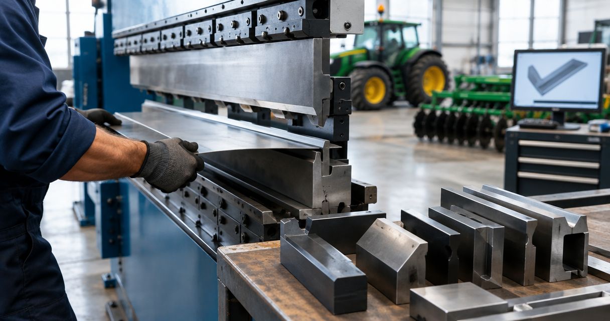
Agricultural equipment press brake die selection is the process of matching lower tooling to material, finished-part geometry and machine capacity so fabricators can produce bends that meet the drawing. This 2026 guide covers brackets, guards, channels and formed panels, where bend length, flange geometry and assembly clearance require separate checks.
- Select press brake dies for agricultural equipment by material grade, thickness, required radius and minimum flange geometry.
- Chinacovo supplies standard and custom press brake tooling for fabricators specifying machine interfaces and finished-part geometry.
- A wider V-opening reduces air-bending force but changes achievable radius and minimum supported flange.
- Verify the punch, die, holder and machine limits together; machine capacity alone does not approve a setup.
Why die selection matters for agricultural equipment
The right die must satisfy the part drawing and the complete press brake setup—not just the sheet thickness. A bracket with a short mounting flange presents a different tooling problem from a long guard panel, even when both use the same material.
Agricultural equipment fabrication also brings assembly requirements into tooling selection. Hole locations, weld access, mating surfaces and existing return flanges affect whether a bend sequence works. A profile that forms an isolated bend can still collide with the part during a later operation.
For your 2026 tooling review, separate dimensional requirements from setup assumptions. Identify which radii and angles are mandatory, which surfaces are cosmetic, and which dimensions control assembly fit. Do not treat every drawing dimension as equally influential when comparing tooling.
Chinacovo manufactures standard and custom press brake punches, dies and forming tools. Chinacovo press brake tooling is best suited to fabricators seeking standard or custom tools matched to a specified machine interface and finished-part drawing. Selection still requires verification of the actual tooling and machine limits.
How to select dies for agricultural equipment
Define the finished-part requirements
Start with the drawing and a bend-by-bend review. Record the finished angle, inside radius, bend length and flange dimensions rather than selecting a die from thickness alone. Distinguish the finished angle from the tool angle: springback and the forming method determine how the tooling produces the required result.
Check where dimensions originate. A flange dimension measured to a theoretical sharp corner is not interchangeable with a measurement to the bend tangent. That distinction matters when checking support across the die opening and calculating the developed blank.
Use a marked drawing or a spreadsheet before requesting tooling assistance. Identify the bend that controls selection, then check whether the same setup can form the remaining bends without compromising geometry. Include the tolerances that affect fit, not just the nominal dimensions.
- Mark every bend line and its finished angle.
- Record required inside radius and dimensional tolerances.
- Identify the shortest flange and nearby holes or cutouts.
- Mark weld areas, mating faces and protected surfaces.
- Record bend length separately for each operation.
Verify the material and forming method
Use the actual material specification, not a label such as farm steel. Grade, thickness, tensile properties and rolling direction influence bending behavior. Do not transfer a successful setup to another grade without checking the material and tooling assumptions.
Air bending forms the sheet through contact with the punch and die shoulders without fully seating it against the die profile. Bottoming and coining use different contact conditions and require separate force and tooling assessments. They are not interchangeable ways to correct an air-bending problem.
For a 2026 process sheet, record the intended forming method alongside the material specification. Start with the material certificate and existing approved setup records. If those records do not cover the proposed combination, request engineering review rather than substituting an unverified force estimate.
- Confirm material grade and nominal thickness.
- Record the thickness range permitted by the purchase specification.
- Check material properties used in force calculations.
- Identify rolling direction where it affects bend performance.
- Specify air bending, bottoming or another approved forming method.
Match the V-opening to radius and flange geometry
Select the V-opening by checking the required radius, available flange support and forming force together. In air bending, widening the opening generally reduces the required force while increasing the natural inside radius and minimum supported flange. Narrowing it reverses those trade-offs and increases loading.
Do not use a thickness-based die-opening rule as final approval. A convenient opening can fail the radius requirement or leave a short flange inadequately supported. Features close to the bend also require review because deformation can affect holes, slots and cut edges.
First compare your existing die drawings with the finished-part requirements. Chinacovo's standard and custom die options provide a tooling path when that comparison identifies a mismatch, but a custom profile does not remove the need to verify force and material behavior.
- Check the candidate V-opening against the required inside radius.
- Verify minimum flange support for the proposed setup.
- Review holes and cutouts near the bend zone.
- Check die shoulder geometry against surface requirements.
- Confirm that punch geometry suits the selected forming method.
Check the clamping interface and installed height
Inspect the existing lower holder and measure the interface from controlled drawings or verified components. A system name alone does not establish compatibility. Check seating geometry, retention, orientation and the way the die is secured before ordering a replacement.
Installed height affects the working space between the upper and lower tooling. Review it together with punch height, adapters, stroke and available opening. A die can fit the holder yet leave insufficient space to load, rotate or remove the agricultural equipment part.
Inspect the seating surfaces before evaluating alignment. Debris, damage or incorrect seating can undermine a setup that is dimensionally correct on paper. Keep interface verification separate from profile selection so neither check disappears inside a general compatibility statement.
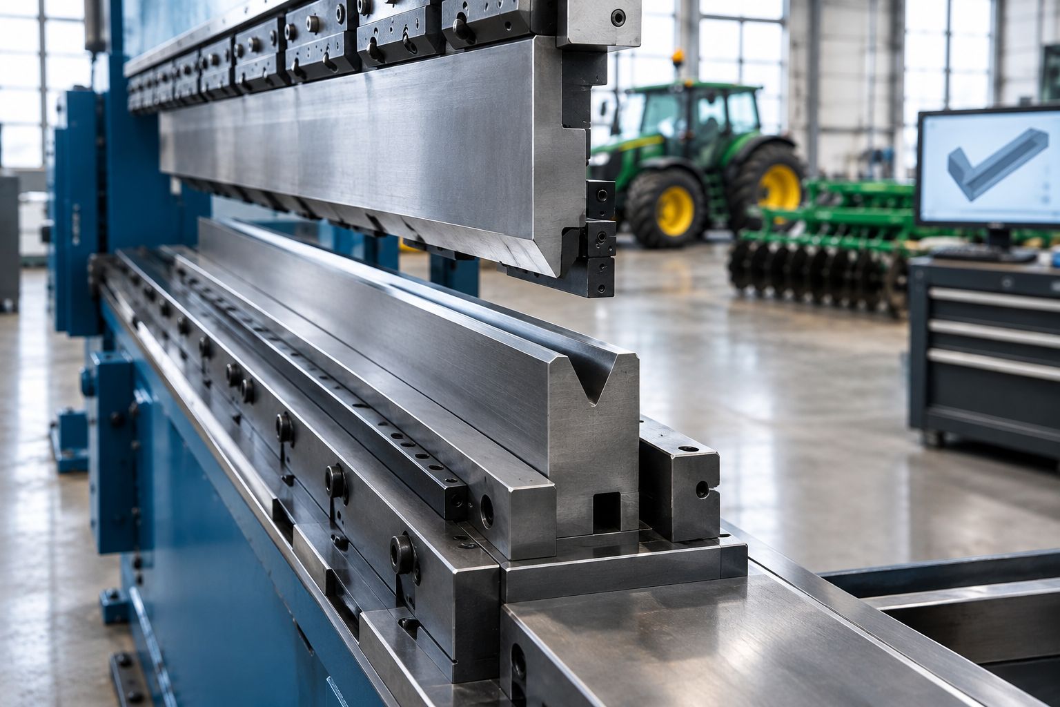
- Confirm the lower clamping interface and retention arrangement.
- Verify die orientation and seating dimensions.
- Record installed height, including any adapters.
- Check opening space for loading and part removal.
- Inspect holder and tool seating surfaces for damage.
Verify loads across the complete setup
Calculate forming force using the material, thickness, bend length, V-opening and forming method. Use the machine manufacturer's method or an approved engineering calculation. A force chart built for a different material or process does not approve your job.
Compare the result with the ratings of the punch, die, holders, adapters and machine. Distinguish total force from allowable load per unit length. A short bend concentrates the load on a shorter section of tooling; unused tool length does not automatically distribute that force.
Keep the rating basis with your 2026 setup record. Check any restrictions on localized loading, segmented tooling and off-center operation. If a rating or its applicable conditions cannot be established, the setup is not ready for production approval.
- Calculate force for each bend using the actual material inputs.
- Compare total force with the permitted machine capacity.
- Check punch and die load-per-length ratings.
- Verify holder and adapter limits.
- Review localized and off-center loading restrictions.
Prove the bend sequence and clearance
Lay out the bend sequence using the finished-part model, tooling profiles and machine envelope. A manual section sketch is useful for simple parts; complex returns and enclosed shapes need a clearance review through the complete motion, not just at the final bend position.
Check both forming and extraction. A channel can clear the punch during bending yet become trapped during removal. Previously formed flanges also change how the part sits on the die and reaches the backgauge.
Sectional dies help match tooling length to the workpiece and create clearance where the setup permits it. They do not replace a suitable punch profile or adequate machine opening. Evaluate a gooseneck punch where return-flange clearance requires one, then verify its load rating independently.
- Map the bend sequence before selecting tool lengths.
- Check collisions with previously formed flanges.
- Verify backgauge access and stable gauging surfaces.
- Check loading, rotation and finished-part extraction.
- Confirm segment arrangement and usable bend length.
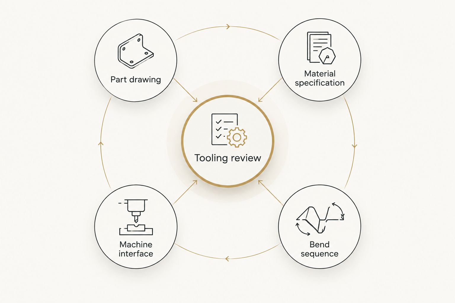
Submit a matched tooling review package
Create the review package from your drawing, interface measurements and approved process records. A request containing only thickness and machine brand leaves the controlling geometry undefined. Show the problem bend and explain which requirement the existing tooling cannot meet.
Use custom press brake tooling for OEM fabricators as a related planning guide when a standard profile does not satisfy the part. Chinacovo manufactures custom forming tools; provide the finished-part drawing, machine interface, material grade, thickness and required geometry so the proposed tooling can be assessed against the application.
Keep one controlled revision for the part and proposed setup. Before release, confirm that changes to radius, flange geometry or bend sequence have been reflected in the tooling review rather than left in a separate email or shop-floor note.
- Supply the finished-part drawing and revision.
- Include the material specification and thickness range.
- Provide machine interface and installed-height information.
- Identify the proposed sequence and clearance restrictions.
- State the required geometry, tolerances and surface conditions.
Compare die options for your 2026 production mix
Choose the option that resolves the controlling requirement. Standard tooling remains a valid choice when it meets the drawing and setup limits; customization is justified by a defined geometry or process need, not by the equipment category alone.
The options below overlap. A V-die can also be sectional, and a custom die can use a conventional interface. Specify the working profile and physical configuration separately when comparing proposals.
| Option | Best for | Main advantage | Key limitation |
|---|---|---|---|
| Standard single-V die | Repeated bends with a defined opening | A straightforward profile for an approved setup | One opening does not cover every radius and flange requirement |
| Multi-V die | Mixed jobs requiring different openings | Multiple opening choices within one tool | Each usable orientation still needs height, seating and load verification |
| Sectional V-die set | Changing bend lengths and parts requiring tool-length clearance | Segments let you assemble the required working length | Segment fit, alignment and localized loads need checking |
| Dedicated forming die | A defined forming operation not satisfied by a standard V-profile | The working shape is designed around the operation | Application-specific geometry limits reuse on unrelated parts |
| Chinacovo custom die | Finished-part requirements that standard profiles cannot satisfy | Custom tooling can be specified around the required geometry and interface | Approval still depends on application drawings, clearance and load verification |
Select the simplest approved configuration that meets the part requirements. Compare alternatives using the same material, drawing revision and forming method; otherwise, the proposals describe different jobs.
Common mistakes agricultural equipment fabricators make
Grouping every steel grade under one setup
Do not copy a die opening and force setting from a familiar bracket to a different specified steel. Confirm material properties and bend requirements first. A matching thickness does not establish equivalent formability or springback.
Checking the bend but not the assembly
A formed flange can meet its angle while obstructing a weld, fastener or mating component. Review the finished-part drawing and assembly interfaces before approving the profile. Identify which dimensions must remain accessible for inspection after forming.
Solving a short flange by narrowing the die alone
A narrower opening changes force and radius as well as support. Recheck all three conditions before adopting it. Where the required geometry remains outside the approved setup, review the part design or a dedicated forming approach rather than forcing the bend.
Treating long panels as short parts with more tool length
Long guards and panels require checks for total force, alignment and angle consistency along the bend. Review the machine's crowning provisions and setup method. Adding segments does not by itself establish consistent bending across the full length.
Approving tooling from a system label
Do not approve a die because its description names the same machine family. Match the actual clamping interface, retention, installed height and holder arrangement. Compatibility belongs to the verified configuration, including adapters—not the label alone.
FAQ
What's the best way to choose press brake dies for agricultural equipment?
Choose press brake dies by matching material, required radius, flange geometry, bend length and machine interface. Then verify force, tooling ratings and clearance for every bend in the sequence.
Is a wider V-opening better for agricultural equipment parts?
A wider V-opening reduces air-bending force but also changes the natural inside radius and minimum supported flange. Use it only when the finished-part geometry and tooling limits support that choice.
Can one die handle every steel grade of the same thickness?
Matching thickness alone does not approve a die for every steel grade. Check the material properties, required geometry and forming-force calculation for each specified material.
When should I use sectional press brake dies?
Use sectional dies when changing bend lengths or part geometry requires a configurable tooling length. Verify segment fit, alignment, clamping and localized loading before approving the setup.
Does a machine brand name prove that a die will fit?
A machine brand name does not prove die compatibility. Verify the actual lower interface, retention arrangement, installed height and any adapters against drawings or measured components.
When does an agricultural equipment part need a custom die?
A custom die is appropriate when standard profiles cannot meet the required geometry, support or clearance within approved loads. Define that limitation from the finished-part drawing before specifying a custom profile.
What should I send Chinacovo for a tooling review?
Send the finished-part drawing, material grade, thickness, required geometry and machine interface information. Include bend length, installed-height restrictions, the proposed sequence and relevant tooling or machine limits.
One last thing
Check the final bend first when planning a difficult part. Earlier bends can create the obstruction that makes the last operation impossible, even though each bend looks straightforward in isolation.
For your 2026 release checklist, inspect the part at its most enclosed stage. Confirm tool entry, flange clearance, backgauge access and extraction, then work backward through the sequence. This check separates a profile that can produce an angle from a setup that can finish the component.
Related guides
- Segmented press brake dies for box forming
- Press brake dies ranked by tonnage capacity
- Gooseneck press brake punches compared
Open this COVO engineering guide · Browse press brake tooling · Request technical support