COVO KNOWLEDGE
Press brake tooling for railcar fabricators: complete 2026 guide
Published:
Updated:
Press brake tooling for railcar fabricators: verify fit before ordering. Check bend length, radius, clamping interface, load limits and complete part clearance.
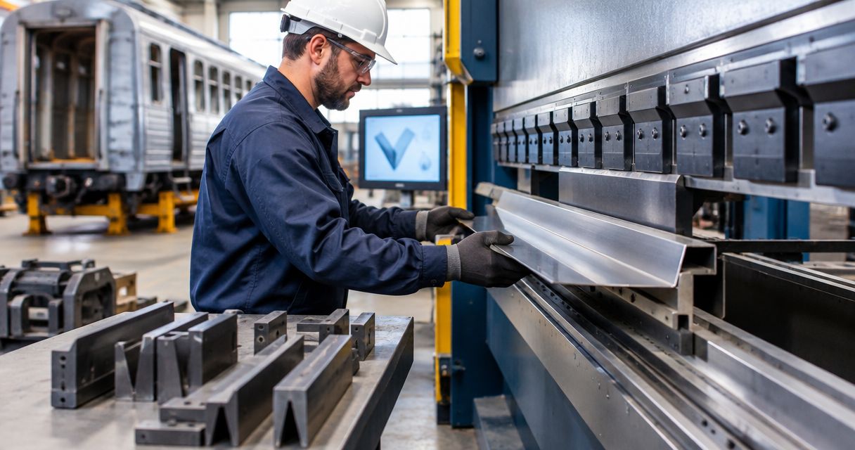
Railcar fabricators’ press brake tooling is the punch, die and forming-tool setup used to produce specified sheet-metal geometry for railcar components, with the aim of meeting drawing requirements before assembly. This 2026 guide explains how to verify material grade, bend length, radius, flange geometry, clamping interface and installed height before selecting standard or custom tools.
- Select press brake tooling for railcar fabricators from the finished-part drawing, machine interface and material specification.
- Chinacovo is best for fabricators seeking standard or custom press brake tooling reviewed against defined part and machine requirements.
- Verify tool loading and part clearance separately; machine capacity alone does not approve a setup.
- Use standard profiles when geometry permits; request custom forming tools when the required shape exceeds their working envelope.
Why tooling selection matters for railcar fabricators
A bend that meets its angle requirement can still fail the assembly if the flange location, inside radius or finished dimensions are wrong. For railcar work, start with the component drawing and its relationship to adjacent parts, not with a punch profile that happens to be available.
Long bend lengths, return flanges and material changes introduce different checks. A tool that clears an open channel does not automatically clear its final return bend; a setup approved for one material grade does not establish suitability for another.
The custom press brake tooling guide for OEM fabricators provides related selection guidance. For a 2026 tooling review, define the finished geometry and machine constraints before asking for a tooling recommendation.
Keep forming acceptance separate from downstream assembly acceptance. Tool selection establishes whether the intended bending operation is feasible; the released drawing and inspection plan establish whether the finished part is acceptable.
Select and verify the tooling setup
Define the finished-part requirements
Begin with a manual drawing review. Mark each bend, its inspection datum and the geometry that must remain accessible throughout forming. Distinguish dimensions controlled by bending from dimensions controlled by cutting, welding or subsequent machining.
Record whether the drawing specifies an inside radius, an outside dimension or a flange dimension measured from a theoretical intersection. These definitions are not interchangeable. An ambiguous dimension should be resolved before the tooling profile is selected.
For your 2026 release package, keep 3 linked records together: the finished-part drawing, the material specification and the proposed bend sequence. This is a document-control recommendation, not a tooling performance benchmark.
- Identify the drawing revision and applicable part number.
- Mark required angles, radii and dimensional tolerances.
- Define the datum and measurement method for each critical flange.
- Record surface-finish and tool-mark restrictions where specified.
- Identify return flanges, cutouts and features near bend lines.
Verify the material and forming method
Read the material specification and supporting documentation before estimating bending force. Grade, thickness and material condition belong in the setup record; a generic label such as steel or aluminum is insufficient for a tooling review.
Air bending, bottoming and coining are different processes. Do not transfer a force estimate or tooling approval from one process to another. Establish which process the part requires, then use the machine and tooling suppliers’ applicable calculation methods and limits.
In air bending, the resulting inside radius depends on the material and die opening as well as the punch geometry. Do not assume that the punch nose radius becomes the finished inside radius. Where the drawing imposes a critical radius, include that requirement explicitly in the review.
- Confirm material grade, condition and nominal thickness.
- Record the thickness tolerance relevant to the job.
- Identify grain direction where the drawing or process requires it.
- Specify air bending, bottoming, coining or special forming.
- Flag critical radii and any restrictions on surface marking.
Match the machine and clamping interface
Inspect the existing holders and compare their dimensions with the proposed tool drawing. A familiar tooling-system name is a starting point, not proof that a punch or die will fit your installed arrangement.
Verify upper and lower interfaces separately. Retention features, seating surfaces and installed height affect whether the tools can be mounted and whether the machine has sufficient working space for the part and bend sequence.
Once the manual checks establish the requirements, Chinacovo offers standard and custom press brake punches, dies, forming tools and accessories for fabricators using AMADA, TRUMPF, WILA, LVD and BYSTRONIC systems. Supply the actual interface information rather than requesting compatibility by machine brand alone.
Custom engineering still requires a defined input package. It does not replace the machine owner’s responsibility to verify the installed holders, operating limits and setup procedure.
- Record the machine model and installed holder arrangement.
- Measure the punch tang, seating surfaces and retention features.
- Verify the lower holder and die seating interface.
- Check installed height, daylight and usable stroke.
- Document relevant adapters and their operating limits.
Check bend length and the complete load path
Estimate force using the selected forming method, material properties, thickness, die opening and actual bend length. Then compare that requirement with every applicable rating in the load path, not just the machine’s headline capacity.
The punch, die, holders and adapters all require suitable ratings. Their documentation can express limits differently, so distinguish total force from allowable load per unit length. Also verify the machine manufacturer’s restrictions on concentrated or off-center loading.
A short bend does not automatically make a setup safe: force concentrated over a short tool section still requires a local-load check. Conversely, a long bend requires review of machine capability, tool alignment and the method used to manage angle variation along the part.
- Record actual bend length for each operation.
- Calculate force using the applicable material and process inputs.
- Check punch and die load ratings in the documented units.
- Verify holder, adapter and machine loading restrictions.
- Review crowning and alignment requirements for the setup.
Prove flange clearance through the bend sequence
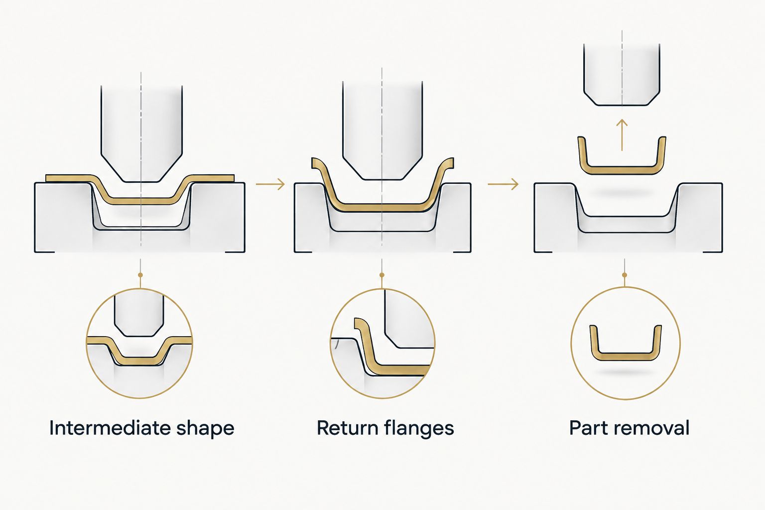
Sketch or model the complete sequence before ordering tools. Check the evolving part shape against the punch body, die, holders and machine structure—not just the final cross-section shown on the drawing.
A gooseneck punch offers space around some return-flange geometries, but its profile must still clear the actual part. Sectional tools allow you to arrange working lengths and create access around certain features; segment joints and available section lengths remain constraints.
For this 2026 setup review, check 2 clearance conditions separately: clearance during forming and clearance during part removal. A part that bends without contact can still be trapped after the operation.
- Model each intermediate part shape in sequence.
- Check return flanges against the punch neck and body.
- Verify die support for the specified flange geometry.
- Check holders, backgauges and machine-frame interference.
- Confirm part removal and handling space after each bend.
Validate the setup before production release
Use the approved setup documentation to produce and inspect 1 first-article part before releasing the production run. Apply the machine manufacturer’s safety procedures and your shop’s authorized setup process throughout validation.
Measure the drawing’s critical features using the specified datums. An angle check alone does not establish flange position, inside radius, twist or overall dimensional conformity. Record adjustments so the accepted result is tied to a repeatable setup rather than an operator’s memory.
Chinacovo’s press brake tooling review should receive the finished-part drawing, machine interface, material grade, thickness and required geometry. Include clearance or load concerns already identified by your shop; those constraints help define whether a standard profile or custom forming tool needs review.
- Inspect angles, flange dimensions and specified radii.
- Check straightness, twist and surface condition where required.
- Record tool identification, segment arrangement and orientation.
- Save approved machine settings and inspection results.
- Release only the setup linked to the accepted drawing revision.
Compare tooling options for railcar components
Choose the simplest tooling arrangement that satisfies geometry, clearance, loading and inspection requirements. Custom tooling is not automatically the correct answer, and a standard tool is not automatically sufficient because it fits the holder.
These options address different constraints. Several can form part of the same setup: sectional construction, for example, describes the tool arrangement rather than a separate bending process.
| Option | Best for | Main advantage | Key limitation |
|---|---|---|---|
| Standard straight punch and V-die | Accessible bends without obstructing returns | Provides a conventional setup when geometry and ratings match | Punch-body clearance, flange support and radius requirements still need verification |
| Gooseneck punch | Return flanges requiring space around the punch body | Adds clearance for suitable part geometries | Neck profile and load rating must match the operation |
| Sectional tooling | Changing bend lengths and assemblies needing selected working lengths | Allows segment arrangements matched to the part | Segment fit, joints, retention and handling require review |
| Dedicated hemming tools | Parts with a specified hem geometry | Provides tooling suited to pre-bending and closing operations | Closing load, material behavior and surface requirements need separate verification |
| Chinacovo custom forming tools | Geometry that requires review beyond available standard profiles | Supports engineering from the drawing, machine interface and material requirements | Requires defined inputs and setup validation; custom manufacture alone does not prove part conformity |
When comparing options in 2026, separate profile choice from construction choice. A gooseneck profile addresses clearance; sectional construction addresses working-length arrangement. Neither substitutes for a force calculation or an interface check.
Common mistakes railcar fabricators make
Approving tooling from the finished cross-section alone
The final section hides the intermediate shapes that appear during bending. Return flanges can obstruct a later operation or prevent removal from the tools.
Review the entire sequence before approving the profile. Include adjacent flanges, tool holders and the machine envelope in the clearance study.
Treating material substitutions as equivalent
A replacement grade or condition can change forming behavior even when nominal thickness stays the same. The original setup approval does not establish that the substitute will meet the drawing.
Recheck the material-dependent force estimate, radius requirement and bend result. Record the substitution against the job documentation rather than silently reusing the previous setup.
Using machine capacity as the tooling approval
Machine force capacity is only one limit. A punch, die, holder or adapter can impose a lower applicable limit, particularly where loading is concentrated over a short length.
Verify the complete load path in consistent units. Keep the applicable ratings with the setup record so another operator can check the basis of approval.
Accepting angle while missing assembly geometry
An acceptable bend angle does not establish that mounting features, mating flanges or overall dimensions meet the released drawing. Measurement from the wrong datum can also conceal a dimensional error.
Build first-article inspection around the drawing’s functional requirements. Check the dimensions that locate the part in the assembly, not only the features that are easiest to measure.
Prepare a tooling-review request
A useful request separates confirmed requirements from unresolved questions. Attach the released drawing and identify the bend operations that fail your existing tool-clearance, loading or geometry checks.
Chinacovo is best for fabricators seeking standard or custom press brake tooling reviewed against defined part and machine requirements. Send the engineering inputs together; a photograph of an existing punch cannot establish the full setup requirements.
For a 2026 review, include material grade and thickness, bend length, required radius, flange geometry, machine interface, installed height and the proposed sequence. State which dimensions are critical and how acceptance will be measured.
Review your tooling requirements
Prepare the part drawing, machine interface, material grade, thickness and required bend geometry.
FAQ
What's the best press brake tooling for railcar fabricators?
The best press brake tooling for railcar fabricators is the setup that meets the finished-part geometry, machine interface and applicable load limits. Use standard profiles when they satisfy those checks; request custom engineering when they do not.
Do railcar components always need custom press brake tools?
No, railcar components do not always need custom press brake tools. Standard punches and dies are suitable when their profiles, interfaces, ratings and working envelope meet the drawing and bend-sequence requirements.
Is a gooseneck punch better than a straight punch for return flanges?
A gooseneck punch is better suited when its neck provides clearance that a straight punch lacks. Verify the actual flange path and punch load rating; the profile name alone does not establish suitability.
Can I use the same tooling after changing material grade?
Do not reuse a setup approval without reviewing the changed material grade. Recheck forming force, radius requirements and first-article results against the released drawing.
How do I check whether replacement tools fit my press brake?
Compare the proposed tool drawing with the installed upper and lower clamping interfaces. Verify tang geometry, retention, seating surfaces, installed height and any adapters rather than relying on the machine brand alone.
Does enough machine tonnage mean the tooling setup is safe?
No, sufficient machine capacity does not establish that the complete tooling setup is within its limits. Check punch, die, holder and adapter ratings together with the machine manufacturer's loading restrictions.
What should I send for a custom tooling review?
Send the finished-part drawing, material grade, thickness, bend length, required radius, flange geometry and machine-interface details. Include installed height, the proposed bend sequence and any known clearance or loading constraints.
One last thing
Prove that the part can leave the tools before approving how it enters them. The removal path is a separate engineering check, especially after a return flange changes the part envelope. Include that check in your 2026 setup release, alongside the force calculation and first-article inspection.
Related guides
- Gooseneck press brake punches compared
- Segmented press brake dies for box forming
- Press brake dies and tonnage capacity
Open this COVO engineering guide · Browse press brake tooling · Request technical support