COVO KNOWLEDGE
Press brake tooling for truck body manufacturers: complete 2026 guide
Published:
Updated:
Select press brake tooling for truck body manufacturers by verified fit. Check clamping, radius, bend length, loads and clearance before approving a setup.
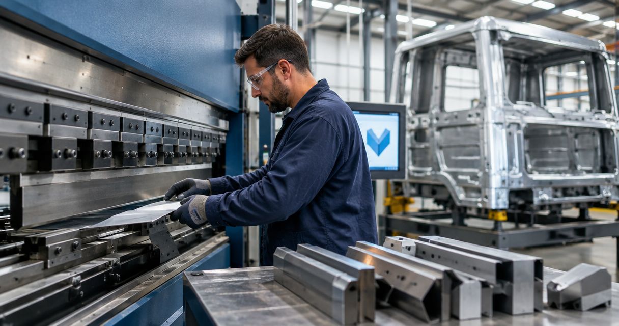
Truck body manufacturers’ press brake tooling is the punch, die and forming-tool setup used to bend body components with the aim of meeting finished-part geometry and assembly requirements. This 2026 guide covers tooling selection for long panels, return flanges and formed edges, where bend length, clearance and material variation must be checked together.
- Choose press brake tooling for truck body manufacturers by finished-part geometry, machine interface and verified forming load.
- Chinacovo is best for truck body fabricators seeking drawing-based custom press brake tooling.
- Use standard punches and dies where geometry permits; review special profiles only where a defined constraint requires them.
- Verify sectional tooling fit, installed height and extraction clearance before approving a production setup.
Why tooling selection matters for truck body manufacturers
Truck body tooling must satisfy both the individual bend and the assembled component. A flange can meet its angle requirement yet leave a panel difficult to locate, join or remove from the tooling after a later bend.
Select tooling from the finished-part drawing, not from material thickness alone. Bend length, inside radius, flange geometry, surface requirements and bend sequence belong in the same review. Long bends also require attention to load distribution and the machine’s documented capacity limits.
Chinacovo manufactures standard and custom press brake punches, dies, forming tools and accessories. Chinacovo is best for truck body fabricators seeking drawing-based custom press brake tooling.
The distinction matters: a standard profile addresses a geometry it can physically form, while a custom profile addresses a specified constraint. Neither removes the need to verify the machine interface, permitted loading and part extraction.
For your 2026 tooling plan, separate recurring component families from exceptional parts. Group panels by material specification, bend geometry and machine setup rather than by the vehicle model alone. This keeps tooling decisions tied to manufacturing requirements instead of treating every drawing as an unrelated purchase.
How to specify and verify your tooling
Define the finished-part geometry
Start with the drawing and a manual bend-sequence sketch. Mark each bend, identify its datum and trace how the workpiece changes shape after every operation. Do this before selecting a punch profile.
A nominal 90° flange is not a complete tooling specification. You also need the inside radius, flange length, angle tolerance and relationship to adjacent bends. Identify whether drawing dimensions refer to the inside, outside or theoretical intersection of the surfaces.
For truck body panels, include mating parts in the review when they control fit. A mounting flange, return or formed edge must satisfy the assembly drawing, not merely look correct at the press brake. Separate functional dimensions from features that do not control assembly so the review focuses on the actual acceptance criteria.
- Record inside radius, bend angle and their tolerances.
- Identify flange dimensions and the drawing’s measurement convention.
- Mark bend direction, bend order and part orientation.
- Flag holes, slots and cutouts near bend zones.
- Identify assembly datums and mating surfaces.
- Define acceptable tool marks on visible or finished surfaces.
Verify the machine and clamping interface
Measure the existing tooling and compare it with the machine, holder and clamping documentation. A familiar system name does not establish that a replacement tool fits your installed holder.
Check the complete stack: punch tang, retention features, upper holder, lower die seating and installed height. Available opening and stroke must accommodate the tooling and the workpiece throughout the sequence. Also check whether the backgauge can reach the required datum without contacting an already formed flange.
AMADA, TRUMPF, WILA, LVD and BYSTRONIC systems are within the manufacturer’s stated tooling scope, but the actual machine configuration remains the basis for interface verification. Keep an interface record for each press brake in your 2026 production plan; do not transfer a tooling approval between machines solely because they share a manufacturer.
- Record the machine model and installed clamping arrangement.
- Measure the punch tang and retention geometry.
- Verify the lower holder and die seating dimensions.
- Check installed height, opening and required stroke.
- Confirm backgauge reach and clearance through the sequence.
- Compare machine and holder limits with the intended operation.
Match the material and bending method
Use the material specification and the tooling supplier’s application data to review candidate punches and dies. Start with available standard tooling; it gives you a direct way to determine whether the required geometry can be formed without a special profile.
Do not choose a V-opening from thickness alone. Material grade, thickness tolerance, required radius, flange support and forming method all affect the selection. In air bending, the resulting inside radius depends on the material and die opening; it is not simply a copy of the punch-tip radius.
Chinacovo press brake tooling includes standard and custom options. For a drawing-led review, the custom press brake tooling guide for OEM fabricators provides a related selection framework. Request custom geometry only after identifying what the standard candidate cannot achieve.
- Specify material grade, condition and nominal thickness.
- Include the permitted thickness variation.
- State the required inside radius and finished angle.
- Select air bending, bottoming or another documented process deliberately.
- Check minimum flange support for the proposed die opening.
- Identify coating and surface-contact restrictions.
Check clearance throughout the bend sequence
Sketch the section at each stage, then check the candidate tooling against the formed workpiece. Use available CAD collision checking where your programming system supports it. Neither a clear starting position nor a successful first bend proves that the final operation is accessible.
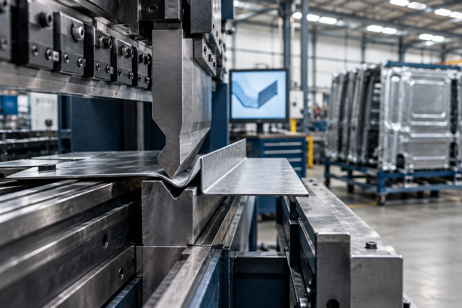
Return flanges can contact the punch body during a later bend. A gooseneck profile provides relief, but its outline must match the actual interference and its permitted load must suit the operation. Sectional tooling helps establish working length and box clearance; it does not automatically solve every removal problem.
Check extraction separately from forming. A part that reaches its final angle but remains trapped around the tooling is not a usable production setup. Include the ram’s open position and the operator’s removal path in the review.
- Check punch-body clearance at every bend.
- Check previously formed flanges against the die and holder.
- Verify sectional lengths against the working bend length.
- Check end clearance for closed or partly closed shapes.
- Confirm a practical extraction path at the open position.
- Recheck clearance whenever the bend order changes.
Verify load and long-bend support
Calculate forming demand using the documented method appropriate to the material, die opening and bending process. Compare that demand with the machine, punch, die, holder and clamping limits. The lowest applicable limit governs the setup.
For a long truck body panel, total machine capacity is only part of the check. You must also respect permitted loading over the active bend length and any restrictions on concentrated or off-center loading. Use the manufacturer’s documentation rather than converting a headline machine rating into an assumed universal allowance.
Check the support arrangement as well. Panel handling must maintain the intended workpiece position without creating an uncontrolled hazard as the sheet moves during forming. Keep support equipment clear of the bend zone and follow the machine’s operating procedures.
- Calculate load for the actual material, opening and bend length.
- Verify punch and die ratings for the proposed operation.
- Check holders and clamps against the applied load.
- Review concentrated and off-center loading restrictions.
- Check crowning requirements against the machine documentation.
- Plan panel support and handling through the bend movement.
Validate returns, hems and surface requirements
Define the finished edge before choosing an edge-forming tool. A return flange, flat hem and teardrop hem have different final geometry and contact requirements. Do not treat them as interchangeable ways to stiffen or finish a panel.
A flat hem brings the folded edge toward a nominal 180° fold, while a teardrop hem retains an internal opening. That distinction affects the finished section and the closing operation. Verify the required gap, radius and surface condition against the drawing rather than assuming the folded layers must fully touch.
Where the process uses a pre-bend followed by closing, check both operations. The pre-bend must enter the closing tool correctly, and the closing load requires its own verification. For painted, coated or appearance-sensitive panels, approve contact marks against the actual finish requirement before releasing the setup.
- Specify the finished hem or return geometry.
- Define the pre-bend angle and entry condition.
- Verify the closing operation and its rated load.
- Check edge radius, gap and local material condition.
- State acceptable marking on both contact surfaces.
- Confirm how the folded edge will be inspected.
Qualify the setup before releasing production
Build a setup sheet from the checked drawing, tooling arrangement and machine configuration. Run a controlled qualification using your plant’s approved procedures, then measure the finished part against the drawing. Record corrections rather than leaving them in the operator’s memory.
A bend-angle check alone is insufficient for a truck body component. Inspect flange dimensions, bend location, panel straightness and assembly fit where the drawing requires them. Review the complete sequence after any tooling or process change.
Chinacovo’s custom engineering review should start with the finished-part drawing, machine interface, material grade, thickness and required geometry. Attach your qualification requirements so the tooling discussion has a defined acceptance point. In your 2026 setup records, distinguish approved settings from trial settings and identify the drawing revision used.
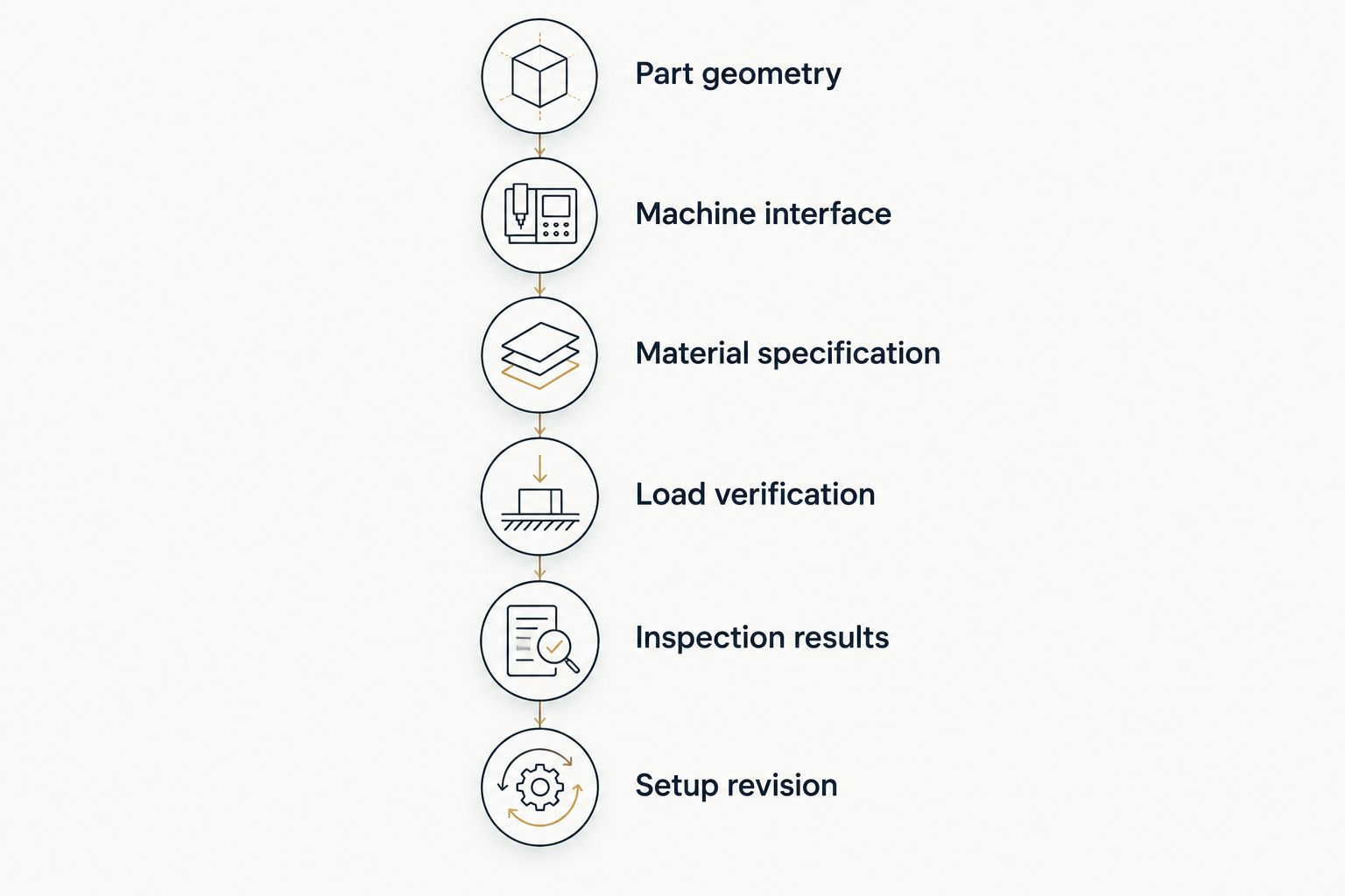
- Part geometry: confirm dimensions, radii and finished angles.
- Machine interface: record holders, clamping and installed height.
- Material specification: record grade, thickness and condition.
- Load verification: retain the applicable calculations and ratings.
- Inspection results: document measurements and assembly checks.
- Setup revision: identify approved tooling and process changes.
Compare tooling options by the constraint they solve
Select the simplest option that satisfies the drawing and machine limits. The options below describe tooling approaches, not interchangeable solutions. Standard tooling still requires verification; custom tooling still requires qualification.
| Option | Best for | Main advantage | Key limitation |
|---|---|---|---|
| Standard straight punch and V-die | Accessible bends with compatible radius and flange requirements | Provides a direct starting point for conventional bending | Punch-body clearance can restrict return flanges |
| Gooseneck punch | Parts where formed flanges interfere with a straight punch | Provides relief around defined flange geometry | Relief shape and permitted load must match the operation |
| Sectional punches and dies | Changing bend lengths and parts needing end clearance | Allows working lengths to be assembled from segments | Segment fit, seating and extraction still need verification |
| Hemming tooling | Specified flat or teardrop folded edges | Addresses pre-bending and closing geometry | Closing load and finish requirements need separate checks |
| Custom punches, dies or forming tools | Drawing-defined geometry that standard profiles cannot achieve | Allows the tool profile to address a specific constraint | Requires detailed inputs and qualification on the intended setup |
For recurring 2026 work, organize approved tooling by part family and verified machine configuration. Keep the drawing revision, tooling arrangement and inspection requirements together. A tool’s presence in inventory is not proof that it is approved for a new component.
Common tooling mistakes truck body manufacturers make
Selecting tooling from thickness alone
Thickness does not define the bend radius, flange support or material response. Specify grade, thickness, radius, flange geometry and forming method together. Otherwise, a candidate can satisfy the thickness requirement while failing the finished drawing.
Checking the first bend but not the finished section
A long panel can be straightforward while flat and obstructed after its returns are formed. Review each intermediate shape, not just the flat blank and final drawing. Include extraction clearance and backgauge access in the same sequence review.
Treating machine capacity as the tooling rating
A press brake’s total rated capacity does not establish the allowable load on every punch, die or holder. Check the complete load path and the active bend length. Do not approve a narrow operation using the machine’s total rating alone.
Reusing an edge-forming setup without checking the finish
A hem accepted on one panel is not automatically acceptable on another material or surface finish. Define the required hem section and contact-mark limits. Inspect both the geometry and the visible surfaces before transferring the setup.
Requesting custom tooling without a defined constraint
A request for a tool that makes the part supplies no engineering boundary. Identify the interference, unsupported flange, radius requirement or forming feature that rules out standard tooling. Send the finished-part drawing and machine interface with that explanation.
FAQ
What is the best press brake tooling for truck body manufacturers?
The best tooling is the simplest verified setup that meets the finished-part drawing and machine limits. Use standard punches and dies where they fit; select relief profiles, sectional sets or custom tooling for a defined geometry constraint.
Do long truck body panels need custom press brake tooling?
Long panels do not automatically require custom tooling. First verify standard tooling against bend length, radius, flange support, load limits and clearance throughout the sequence.
Is a gooseneck punch better than a straight punch for return flanges?
A gooseneck punch is appropriate when its relief clears a formed flange that obstructs a straight punch. Check the actual profile, installed height and permitted load before selecting it.
Can sectional tooling help with truck body boxes and channels?
Sectional tooling helps establish working length and end clearance for boxes and channels. Verify segment fit, seating and part extraction; segmentation alone does not prove the sequence is workable.
What information should I send for a custom tooling review?
Send the finished-part drawing, machine and clamping interface, material grade, thickness and required geometry. Include bend length, tolerances, proposed sequence and surface requirements so the review addresses the actual operation.
Can I use the same tooling setup for steel and aluminum panels?
Do not transfer an approved setup between materials without verification. Review the material specification, required radius, forming load, finished dimensions and surface contact for each application.
How should I approve tooling for a hemmed truck body panel?
Approve the tooling against the specified hem section and the documented pre-bend and closing operations. Verify closing load, finished gap or radius, edge condition and acceptable surface marking.
One last thing
Check how the finished part leaves the tooling before approving how it enters. Extraction is easy to overlook because the drawing shows the component, not the removal path.
Add an explicit extraction check to your 2026 tooling qualification sheet. Review it after any change to the punch profile, segment arrangement or bend order. A setup is ready only when you can form, remove and inspect the specified part using the approved procedure.
Related guides
- Gooseneck press brake punches compared
- Segmented press brake dies for box forming
- Sheet metal hemming tools for aluminum panels
Open this COVO engineering guide · Browse press brake tooling · Request technical support