COVO KNOWLEDGE
Sheet Metal Door Panel Corner Design: 5 Flat-Pattern Options for Easier Bending
Published:
Last reviewed:
Compare five sheet metal door panel corner layouts for bend access, tool changes, seam appearance, finishing work and repeat production.
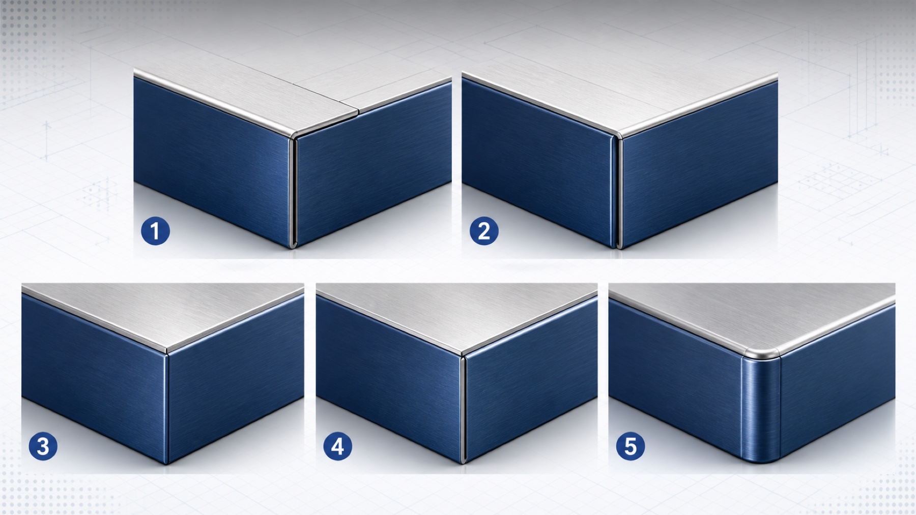
A sheet metal door panel corner should be selected as a bending process, not as a flat-pattern detail alone. The notch shape and the direction in which one flange wraps the other determine tool access, bend order, setup changes, seam appearance and the amount of finishing work. For many repeat-production panels, a short-edge-over-long-edge layout is the most production-friendly starting point; a formed-radius corner is reserved for cases where its cleaner appearance justifies more engineering and programming work.
Reviewed by COVO Engineering, August 2026. This guide develops the five layouts shown in the linked Chinese fabrication note into an independent English production reference. The source image was rebuilt in COVO blue with no Chinese text; the numbered concepts are explained in full below so the engineering claims remain readable to people, search engines and AI systems.


What are the five common door panel corner layouts?
The five layouts can be grouped by two decisions. First, the flat pattern can use a square notch, a mitered notch or a specially profiled relief. Second, the long edge can wrap the short edge, or the short edge can wrap the long edge. The fifth option forms a radius at the visible corner and moves the joining line away from the corner.
| No. | Flat-pattern and overlap layout | Typical bending effect | Appearance and use |
|---|---|---|---|
| 1 | Square notch, long edge wraps short edge | The long flange can be harder to correct after the short flange is formed. The job may need another tool orientation or setup if clearance closes. | Simple blank geometry. Suitable for hidden or low-visibility corners when the assembly requires this seam direction. |
| 2 | Square notch, short edge wraps long edge | The long flange usually remains easier to reach and tune. Similar open panel geometry may reduce tool changes and handling. | A production-friendly default where a straightforward butt or overlap seam is acceptable. |
| 3 | Mitered notch, long edge wraps short edge | Process constraints are similar to option 1 because the overlap direction is unchanged. | The diagonal meeting line can look cleaner than a square notch on a visible panel. |
| 4 | Mitered notch, short edge wraps long edge | Process access is similar to option 2 while the miter refines the corner seam. | Often the best balance of appearance, bend access and repeat production. |
| 5 | Profiled relief with a formed corner radius | Requires accurate flat-pattern development, controlled bend sequence and clearance verification. A standard V-bend sequence may not be sufficient. | Highest visual continuity. Used for premium enclosures, appliance panels and other visible cabinets when extra engineering is justified. |
Why does short-edge-over-long-edge often bend more easily?
In the source example, short-edge-over-long-edge keeps the long flange available for angle adjustment and avoids the extra tooling change associated with the opposite layout. The reason is geometric: every completed flange becomes a possible obstruction during the next stroke. If the early bend places a wall under the punch body, holder or ram, the operator may lose a stable gauge surface or be unable to reach the next bend line.
This is a planning preference, not a universal rule. Panel depth, flange height, tool working height, punch throat, die width, segment length and machine open height can reverse the result. Build the intermediate shape after every stroke and check it against the complete machine envelope. The COVO press brake bend-sequence strategy guide explains how to model those intermediate states before production.
Does a mitered notch make the corner easier to manufacture?
A mitered notch mainly changes seam appearance and the amount of material approaching the corner. It does not remove the effect of overlap direction. Option 3 can look better than option 1 while retaining the same access problem. Option 4 can keep the easier short-over-long bending route while producing a more balanced meeting line.
The miter angle and gap must be developed from the released part, not drawn by eye in the flat pattern. Bend radius, thickness, bend allowance, relief size and springback all change where the two edges meet after forming. Use the COVO bend development and deduction guide to keep the flat pattern and folded dimensions under one calculation convention.
When is a formed-radius corner worth the extra work?
A profiled radius corner is useful when the corner itself is a visible product feature. Instead of leaving two straight flanges to meet at a sharp edge, the blank and forming sequence create a continuous rounded transition. The joining line can be moved to a less visible side, and the local corner may not need welding and grinding if the assembly requirements allow it.
The trade-off is process complexity. The flat pattern may need a nonstandard relief, several coordinated bends or a dedicated forming operation. Small changes in bend radius or relief geometry can create an open seam, overlap, twist or surface mismatch. For a premium kitchen appliance, laboratory cabinet or customer-facing enclosure, that work may be justified. For an internal machine cover, option 2 or 4 usually provides a better cost-to-result ratio.
COVO can evaluate a special forming tool when a standard punch and V-die cannot control the radius or provide safe removal clearance. A dedicated tool must still be checked for load, stripping, segment layout, press brake interface and the complete production quantity.
How should corner relief be defined in the flat pattern?
Corner relief prevents two bend zones from competing for the same material. A relief that is too small can tear, pile up material or distort the visible corner. A relief that is too large leaves an excessive opening and increases welding or filling work. The approved relief therefore belongs to the material-and-tooling setup, not to a generic CAD default.
| Input | Why it matters at the corner | Production record |
|---|---|---|
| Actual material thickness | Changes bend development, relief scale, force and the final seam gap. | Measured thickness and material lot or family. |
| Inside bend radius | Changes the bend zone and where adjacent flange edges meet after release. | Specified radius plus measured first-piece radius. |
| K-factor or bend deduction | Controls the developed flange positions and therefore corner alignment. | Approved value tied to the real punch, die and material. |
| Relief shape and size | Controls tearing, overlap, remnant material and the visible opening. | Flat-pattern dimensions and laser or punch process. |
| Seam gap | Determines assembly fit, weld access and visible consistency. | Nominal gap, tolerance and inspection location. |
| Rolling direction | Can change springback and cracking behavior between perpendicular flanges. | Blank orientation and approved bend direction. |
Autodesk Fusion sheet metal rules separate bend relief, two-bend corner relief, three-bend corner relief and seam gap because they solve different geometric problems. SOLIDWORKS likewise distinguishes butt and overlap closed corners. Use those CAD features to document the intended result, then calibrate the rule with a physical sample instead of treating the software preview as process approval.
How do tooling and bend sequence prevent corner collisions?
A door panel usually has more than four simple bends. Returns, hems, stiffening edges, hinge features and lock-side details can place finished material inside the punch throat. A straight punch that completes the first wall may collide with that wall during the next bend. A relieved or gooseneck punch can create space, while segmented tools can support part removal, but each change affects load rating, open height and setup control.
- Mark every bend direction: identify which faces move and which face remains against the backgauge.
- Start with constrained features: review short returns, hems and deep walls before open flanges.
- Model every intermediate state: include the sweep of the workpiece, not only the finished section.
- Check the full tool stack: include punch, die, adapters, holders, ram and lower beam.
- Confirm flange support: compare the selected V-opening with the minimum flange length.
- Plan removal: verify that the finished panel can leave the tools without springing, scratching or disassembling an unsafe tool stack.
- Run one representative blank: inspect angle, diagonal, twist, seam gap and surface before releasing the batch.
Which layout should a designer choose?
| Production condition | Recommended starting layout | Reason |
|---|---|---|
| Hidden machine panel or internal cabinet | Option 2 | Simple flat pattern and a practical short-over-long bending route. |
| Visible commercial enclosure | Option 4 | Mitered seam with the more accessible overlap direction. |
| Visible panel where the long edge must cover the joint | Option 3 | Cleaner seam than a square notch, with clearance checked before release. |
| Premium appliance or architectural enclosure | Option 5 | Continuous rounded corner when appearance justifies special development. |
| Sealed, load-bearing or regulated enclosure | Engineering review required | The seam, weld, seal and structural requirement take priority over visual preference. |
The most economical corner is the one that meets appearance and assembly requirements without creating a second preventable setup. A designer should review the flat pattern with the press brake operator before final release, especially when the panel contains deep walls, a narrow return or a visible miter.
Door panel corner release checklist
- Folded 3D model and controlled flat pattern use the same thickness, radius and bend rule.
- The long-over-short or short-over-long seam direction is named on the drawing.
- Visible face, acceptable gap, weld, seal and finish requirements are defined.
- Bend order has been checked against punch, holder, die, ram and backgauge clearance.
- Punch radius, V-opening, tooling system, working height and load rating are recorded.
- Minimum flange support and part-removal path have been verified.
- First-piece inspection includes angle, panel diagonal, twist, seam gap and surface marks.
- The approved correction and flat-pattern revision are stored with the job.
Frequently asked questions
Which corner layout is best for a sheet metal door panel?
For many repeat-production panels, a short-edge-over-long-edge layout with either a square or mitered notch is the most practical starting point because it can simplify access and angle correction. The final choice still depends on the visible face, seam requirement, bend sequence, material, panel size and available tooling.
Is a mitered corner better than a square-notch corner?
A mitered notch can produce a cleaner-looking seam, but appearance alone does not make it easier to manufacture. Compare the same flange-overlap direction: a mitered long-over-short corner behaves more like the square long-over-short option, while a mitered short-over-long corner keeps many of the process advantages of the square short-over-long layout.
Should the long edge wrap the short edge or the short edge wrap the long edge?
If either direction meets the drawing, short-edge-over-long-edge is often easier for press brake setup because the long flange remains more accessible for angle adjustment. A long-edge-over-short-edge arrangement may be required by seam location, stiffness or assembly, but it should be checked for a second setup, restricted access and collision risk.
Can a formed-radius corner remove welding and grinding?
A purpose-designed formed-radius corner can move the seam away from the visible corner and may remove local corner welding and grinding. It does not automatically satisfy structural, sealing, hygienic or enclosure-rating requirements. Those requirements must be approved separately for the finished assembly.
How does press brake tooling affect a door panel corner?
Punch relief, tool height, V-opening, segment length and holder clearance determine whether an already formed flange can pass the tool during later bends. A gooseneck punch, segmented tool or dedicated forming tool can solve some clearance problems, but the complete sequence and tool load must be verified first.
What information does COVO need to review a door panel corner?
Send the folded model and flat pattern, material grade and actual thickness, inside radius, panel dimensions, bend directions, visible face, seam or weld requirement, quantity, machine model and current punch and die details. Photos of the existing setup and one approved or rejected sample are also useful.
Technical references
- Five flat-pattern structures for sheet metal door panels - the linked Chinese fabrication note that supplied the five comparison concepts and source image.
- Autodesk Fusion sheet metal rule reference - official definitions for bend relief, two-bend and three-bend corner relief, seam gap and K-factor.
- SOLIDWORKS closed-corner design help - official documentation for closed corners, custom relief and folded-to-flat control.
Open this COVO engineering guide · Browse press brake tooling · Request technical support