COVO KNOWLEDGE
Oscillating Dies for Press Brakes: How Rotating Supports Improve Bending
Published:
Last reviewed:
Learn how oscillating press brake dies use rotating supports to reduce marking, form shorter flanges and protect holes, plus selection and maintenance checks.
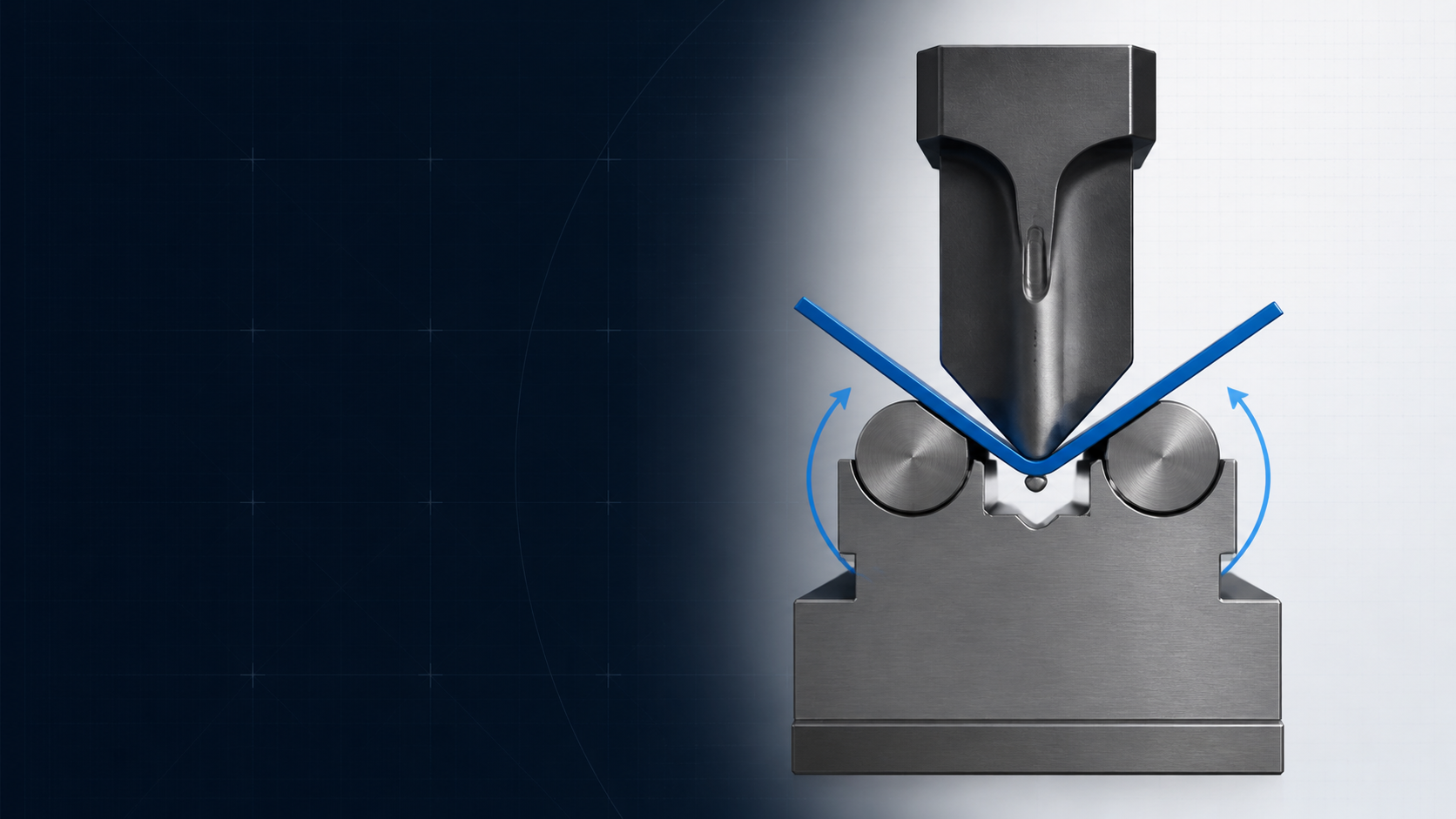
An oscillating press brake die uses two rotating supports to guide the sheet as the punch forms the bend. By converting much of the sliding contact found at fixed V-die shoulders into controlled rotation, the design can reduce surface marking, support shorter flanges and protect geometry near holes or oblique edges. It is a specialist option, not a universal replacement for a conventional V-die.


What is an oscillating press brake die?
An oscillating die is a lower press brake tool built around two movable support elements. Depending on the manufacturer, those elements may be called rollers, rotors, wings or oscillating halves. Their exact profile and return mechanism vary, but the production idea is consistent: the sheet begins on broad upper supports, and those supports rotate as the punch drives the bend.
In a conventional fixed V-die, the sheet is supported at two stationary shoulders. As the flange rises, the contact point moves and the material slides across the shoulders. An oscillating design allows the supporting surfaces to follow more of that motion. It does not eliminate friction, pressure or tooling marks, but it changes the contact path in a way that can be useful for sensitive surfaces and difficult edge geometry.
The term must also be kept in context. This guide discusses a press brake rotating-support bending die. It is not the oscillating cutoff die used in a coil blanking line, and it is not the same as an adjustable V-die whose opening is changed by repositioning fixed blocks.
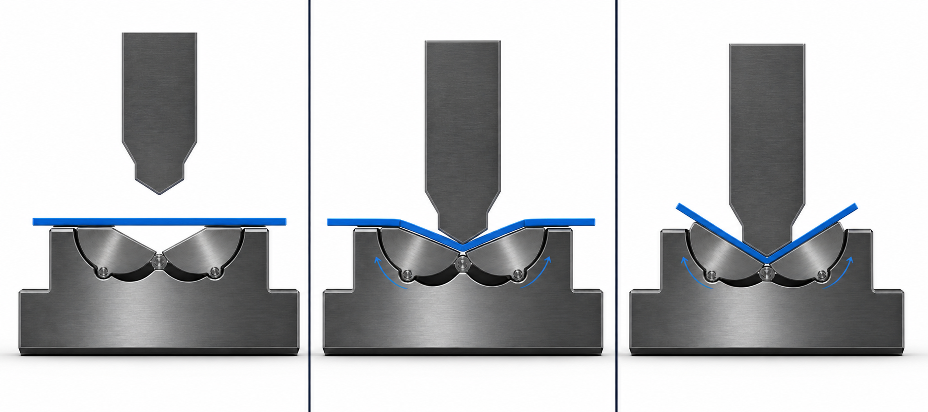
How does the oscillating action work?
- Flat loading: the blank rests across the upper faces of the two supports. The tooling centerline, bend line and backgauge datum must already be aligned.
- Punch contact: the punch touches the sheet and starts to move the bend zone downward. Both sides should load symmetrically unless the selected product is specifically approved for another condition.
- Controlled rotation: each support turns in its machined seat as the flange rises. The surface follows the sheet instead of remaining a fixed shoulder under a sliding flange.
- Bottom position: the punch depth, support geometry and material response create the loaded angle. The released angle still includes springback and must be measured after unloading.
- Return: when the ram rises, the supports return to their loading position through the mechanism built into that tool. Confirm full, synchronized return before the next blank is placed.
This sequence is why cleanliness and free movement matter. A chip under one support, a damaged pivot or an incomplete return changes the contact geometry before the controller has changed any programmed value. A ram-depth correction cannot repair a support that is not rotating as designed.
What production problems can rotating supports solve?
| Production need | How the oscillating die may help | What still needs verification |
|---|---|---|
| Visible or coated surface | Less sliding at fixed shoulders can reduce scuffing and deep witness lines. | Tool cleanliness, burr direction, film behavior, contact pressure and the accepted finish sample. |
| Short flange | The rotating supports can continue to carry a flange that would not bridge a comparable fixed V-opening. | Published minimum flange, backgauge access, punch clearance and safe part support. |
| Hole or slot near the bend | Continuous support and lower sliding drag can reduce stretching around nearby cut features. | Feature size, edge distance, material ductility, grain direction and finished tolerance. |
| Oblique or tapered edge | Moving supports can guide irregular edge contact more smoothly than two fixed shoulders. | Stable loading, tool length, local pressure, part twist and whether the edge stays supported throughout the stroke. |
| Patterned or polished sheet | Broader moving contact can help protect a texture or cosmetic finish. | A representative test coupon; "reduced marking" must not be treated as a guaranteed mark-free result. |
Surface finish: reduce the sliding mechanism, not the inspection
Oscillating dies are often grouped with mark-reduction and mark-free bending solutions. The label is useful for search and application planning, but it should not become an absolute promise. Dirt, scale, laser dross, burrs, worn support faces and high local load can still print into the part. Polished stainless, anodized aluminium, pre-painted steel and decorative sheet should be approved against a retained first-piece sample under production lighting.
Short flanges and features near the bend line
A fixed V-die requires enough material to remain supported on both shoulders at the beginning of the stroke. The moving supports of an oscillating die can change that requirement and often make a shorter flange practical. The same support principle can limit the pull that distorts a hole or slot near the bend. Neither benefit can be reduced to one universal multiplier: use the selected tool's geometry and verify the exact flat layout.
For an early conventional-die comparison, review the COVO V-opening, minimum-flange and tonnage guide. Then replace its generic assumptions with the oscillating die manufacturer's load and flange data before production release.
Oscillating die vs conventional V-die
| Decision factor | Oscillating die | Conventional fixed V-die |
|---|---|---|
| Sheet support | Two support elements rotate with the developing flanges. | The sheet moves across two fixed die shoulders. |
| Surface contact | Can reduce sliding marks when the tool and sheet are clean. | Stable and familiar, but shoulder sliding may mark sensitive finishes. |
| Minimum flange | Often shorter for an equivalent application, subject to model data. | Controlled by the opening, shoulder geometry and available blank support. |
| Near-hole behavior | Can reduce drag-related distortion close to the bend. | A nearby feature can stretch as the sheet moves over the shoulders. |
| Tool envelope | The body may be wider and the working height may create clearance constraints. | Many compact profiles, heights and openings are widely available. |
| Close reverse bends | Body width can interfere with a tight Z or closely spaced second bend. | A narrow die or dedicated offset tool may provide better access. |
| Maintenance | Rotating surfaces, seats and return components need inspection. | Primarily working faces, shoulders, tangs, seating and straightness. |
| Process history | Requires tool-specific setup data and a controlled first article. | Often already represented in the shop's bend tables and programs. |
How does roller center distance relate to V-opening?
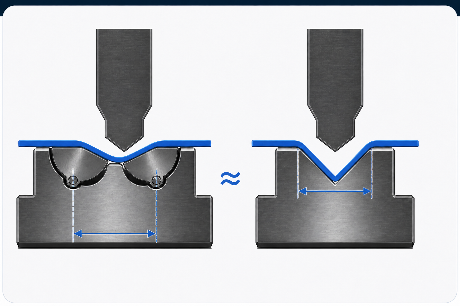
The book section provides a useful workshop approximation: identify the two rotation centers, measure their center-to-center spacing, and compare that distance with the nominal width of a conventional V-die. In its example, an observed spacing of about 15.5 mm is treated approximately like a 16 mm, 88-degree V-die for bend-radius planning.
The same caution applies to radius. The book states that an oscillating die can generate a bend radius comparable with a conventional die whose V width matches the support center distance. "Comparable" is not "identical." Measure the released inside radius and connect it to the flat-pattern values actually used for the job. The COVO angle-control and springback guide explains why a correct loaded shape can still recover to a different finished angle.
Where are oscillating dies most useful?
- Cosmetic panels: polished stainless steel, aluminium and other visible faces where shoulder witness lines create rework.
- Pre-finished sheet: coated, pre-painted or film-protected stock where the process must preserve the delivered surface.
- Short-flange parts: brackets and enclosures whose flange cannot be reliably supported over the preferred conventional opening.
- Perforated geometry: bends located close to holes, slots, notches or perforations that are vulnerable to drag-related distortion.
- Tapered or oblique blanks: parts whose edge reaches the two sides of a fixed V-die at different positions.
- Patterned surfaces: tread or decorative sheet where a stable support path is preferable to concentrated shoulder sliding.
These are candidate applications, not automatic approvals. A polyurethane insert, protective film, polished-radius die, adjustable die, special forming tool or a different bend sequence may solve the same production problem with a better machine envelope. Compare the complete set of COVO special tooling options before committing the part to one mechanism.
What are the limitations?
Wide body and close Z-bend clearance
The book identifies die width as a primary disadvantage because a broad body can block a closely spaced reverse bend. Model both the first and second formed states, including the full lower-die body, punch, clamp and table. A narrow fixed die or a dedicated one-stroke Z-bending tool may be the cleaner solution.
Tool height and machine daylight
The referenced design is also described as relatively low. Whether low height is a disadvantage depends on the machine stack and finished profile: it can change punch reach, holder requirements, backgauge access and the room available to rotate or remove the part. An adapter can add height, but it also adds an interface and consumes open height. Check the assembled stack, not the die alone.
Moving components and product-specific rules
A rotating-support die has more functional surfaces than a solid V-block. Seats, pivots, springs or other return parts must move freely and remain synchronized. Loading rules also vary. For example, one commercial product may specify a minimum percentage of its tool length in use or a spring-related load correction; those limits belong to that product and must not be generalized to every oscillating die.
Oscillating die selection checklist
- Material: grade, tensile or yield-strength range, actual thickness, temper, grain direction and burr orientation.
- Surface: polished, coated, pre-painted, anodized, film-protected, patterned or otherwise cosmetic.
- Finished bend: target angle, inside radius, angle tolerance, flange tolerance and acceptable surface sample.
- Blank geometry: shortest flange plus the size and bend-line distance of every hole, slot, notch or oblique edge.
- Working length: full bend length, shortest part, segment plan, joint position and any possibility of off-center loading.
- Equivalent opening: support center distance and the manufacturer-defined relationship to radius, flange and load.
- Upper tool: punch angle, nose radius, profile clearance, height and rated load.
- Lower interface: die base, holder, table, adapter, centerline and clamping method.
- Machine envelope: open height, stroke, daylight, backgauge access, support system and finished-part removal path.
- Capacity: required force for the real material and loaded length, checked against every machine and tooling rating.
Send these inputs with the part section rather than asking only for an "oscillating V16." A nominal equivalent opening does not identify the body width, support profile, tool height, interface or safe load. COVO can compare the application with standard press brake dies, mark-reduction tooling and a purpose-built special die.
Setup, first-article and maintenance workflow
- Inspect before installation. Check the die body, rotating faces, seats, return mechanism, tang or base and segment joints for damage or contamination.
- Confirm free movement. With the machine in a safe service condition, verify that both supports move smoothly and return completely according to the tool manufacturer's procedure.
- Clean the blank and tooling. Remove chips, scale, dross and adhesive debris. Do not trap particles under a visible surface or moving support.
- Center and clamp the complete stack. Verify the lower-tool datum, punch centerline, holder, adapter and loaded segment arrangement.
- Check force and interference. Use the actual bend length and material; model close returns, holes, hardware and the removal path.
- Run a controlled first bend. Use the machine-specific safe setup mode and approved safeguarding. Observe support motion without entering the point of operation.
- Inspect after release. Measure angle, radius, flange dimensions and near-hole geometry, then inspect the surface under the agreed lighting.
- Record and maintain. Store the tool identity, material lot, program correction, inspection result and maintenance action for the next run.
Lubrication intervals are product-specific. Follow the selected tool's manual rather than importing a cycle count from another manufacturer. Before cleaning, lubricating or adjusting the die, isolate hazardous energy under the applicable lockout procedure. Rotating supports do not remove the press brake point-of-operation, pinch, moving-workpiece or overload hazards.
When should you choose an oscillating die?
Choose it for engineering review when a conventional V-die produces unacceptable shoulder marks, cannot support the required flange, distorts nearby cut features or handles an oblique edge poorly. Keep the conventional route in consideration when the part needs close Z-bend access, minimum tool width, maximum standard availability, a proven existing bend table or simple maintenance. The best decision is the tool that satisfies geometry, surface, load, clearance and repeatability together.
For the broader process choice, compare air bending and bottoming. An oscillating lower die changes how the sheet is supported; it does not by itself decide the final bending method, springback strategy or inspection plan.
Frequently asked questions
What is an oscillating die for a press brake?
An oscillating die is a press brake lower tool with two rotating or pivoting support elements. The sheet starts on their upper surfaces; as the punch descends, the supports rotate with the developing bend and continue to guide the material.
How is an oscillating die different from a conventional V-die?
A conventional V-die has fixed shoulders, so the sheet moves across those stationary contact areas during air bending. An oscillating die replaces much of that sliding action with controlled rotating support. The two designs also have different flange, height, clearance, load and maintenance requirements.
Does an oscillating die guarantee mark-free bending?
No. Rotating support can reduce the sliding marks associated with fixed die shoulders, but surface results still depend on sheet finish, burrs, dirt, tool condition, contact pressure, protective film and handling. A representative first-piece test is required for any visible-surface specification.
Can an oscillating die bend a shorter flange?
It can often support a shorter flange than a conventional V-die used for the same thickness because the moving supports continue to carry the sheet as they rotate. The exact minimum flange is model- and application-specific and must be taken from the approved tool data or a controlled trial.
Can rotating supports reduce distortion near holes and cutouts?
They can help because the sheet is continuously supported and experiences less sliding drag near the bend line. The result depends on hole size, edge distance, material, grain direction, bend angle and support geometry, so the drawing and first article still need review.
How is the equivalent V-opening of an oscillating die selected?
A useful planning approximation compares the center-to-center distance of the two rotating supports with the opening of a conventional V-die. It is not a complete specification: the actual tool geometry, punch radius, material, target angle, load chart and manufacturer instructions still control the setup.
Does an oscillating die always require less tonnage?
No universal tonnage advantage applies to every oscillating-die design. Springs, support geometry, friction, material and working length can change the load. Calculate from the selected tool manufacturer's current data and stay below the lowest rating in the press, clamp, punch, die and loaded segment.
Which materials are suitable for oscillating dies?
They are commonly evaluated for polished stainless steel, aluminium, coated or pre-painted sheet, film-protected sheet and patterned surfaces, as well as parts with short flanges or nearby openings. Suitability must be confirmed for the actual grade, thickness and finish.
When is a conventional V-die the better choice?
A conventional V-die may be preferable when the job needs close reverse or Z bends, maximum open-height efficiency, the broadest standard-tool availability, simple maintenance or a geometry already proven in production. Choose by the complete part and machine envelope, not surface marking alone.
Is an oscillating die compatible with every press brake?
No. Confirm the lower-tool interface, holder or table, tool height, open height, stroke, centerline, usable length, segmentation, machine control and load capacity. An adapter may solve an interface mismatch but also changes height and the number of loaded joints.
How should an oscillating die be maintained?
Keep the support faces, pivots, seats and return mechanism clean; remove chips and material transfer; verify smooth synchronized rotation and full return; inspect segments and clamps; and use only the lubricant and interval specified for that tool. Do not copy another brand's maintenance cycle into an unverified setup.
Does an oscillating die remove normal press brake hazards?
No. Point-of-operation, pinch, moving-workpiece, overload and tool-handling hazards remain. Only trained personnel should operate the setup, all machine safeguards must remain active, and lockout procedures apply before cleaning, lubrication, adjustment or service.
Technical references
This article is an original COVO engineering interpretation of the "Oscillating dies" section and Figure 7.9 in Sheet Metal Bending by Emiliano Corrieri. The three illustrations were newly composed in the COVO visual system from the mechanism described in that section; they are conceptual, not dimensional copies or commercial product drawings.
Application claims were cross-checked against current rotating-support tooling guidance from Rolleri, Mate Precision Technologies and WILA. These sources describe their own products and selection methods; their numeric limits are not COVO specifications. Production approval must use the chosen tool drawing, machine manual, material data and a controlled first article.
Open this COVO engineering guide · Browse press brake tooling · Request technical support