COVO KNOWLEDGE
Bend Allowance vs Bend Deduction: Formulas, Worked Example and Test-Strip Check
Published:
Updated:
Bend allowance adds to the flats; bend deduction subtracts from outside dimensions. Formulas, a 2 mm worked example and a 100 mm test-strip check.
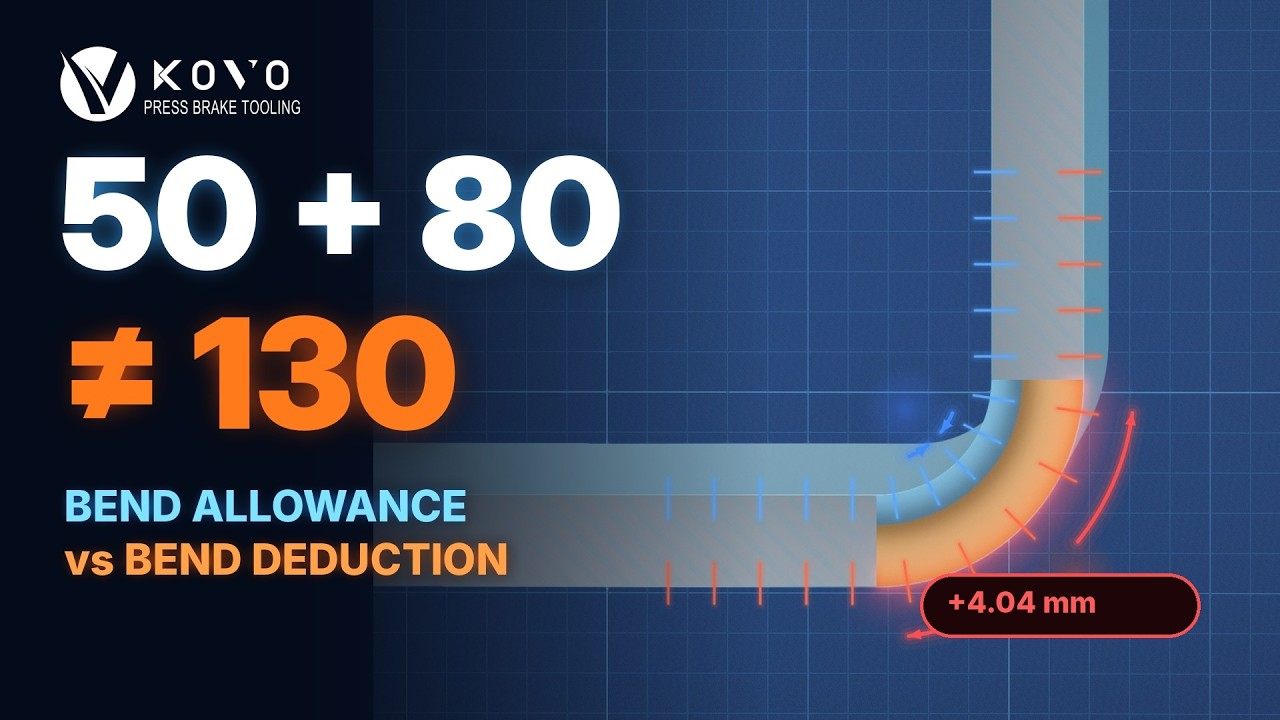
Direct answer: Bend allowance and bend deduction are two routes to the same flat blank. Bend allowance (BA) is the length of the neutral axis through the bend, and you add it to the straight flats. Bend deduction (BD) is what you subtract from the sum of the outside dimensions on the drawing. For 2 mm steel bent to 90° in a 16 mm V die (inside radius about 2.5 mm, K-factor 0.33), BA = 4.96 mm and BD = 4.04 mm, so a 50 × 80 mm angle needs a 125.96 mm blank, not 130 mm.
What the video covers:
- 0:00 Why a 130 mm blank makes a 50 × 80 mm part about 4 mm too big
- 0:29 The neutral axis and the K-factor
- 0:58 Bend allowance formula and the worked example
- 1:44 Virtual sharp, outside setback and bend deduction
- 2:16 Same blank by both routes, and one deduction per bend
- 2:46 Measuring your own bend deduction with a 100 mm test strip
Bend allowance vs bend deduction at a glance
| Bend allowance (BA) | Bend deduction (BD) | |
|---|---|---|
| What it is | Length of the neutral axis through the bend, from one bend line to the other | How much the outside dimensions overstate the blank, for one bend |
| Start from | Flat lengths between the bend lines (tangent points) | Outside dimensions measured to the virtual sharp |
| Operation | Add one BA per bend | Subtract one BD per bend |
| Formula | BA = A × π / 180 × (ri + K × t) | BD = 2 × OSSB − BA, with OSSB = (ri + t) × tan(A / 2) |
| Video example | 45.50 + 75.50 + 4.96 = 125.96 mm | 50 + 80 − 4.04 = 125.96 mm |
| Calculator | Bend allowance calculator | Bend deduction calculator |
A is the bend angle in degrees, ri the inside radius, t the material thickness and K the K-factor. OSSB is the outside setback.
Why 50 + 80 is not 130
A drawing of an L-bracket usually gives outside dimensions: 50 mm and 80 mm, each measured to the virtual sharp, the point where the two outer faces would meet if the corner were square. Adding them gives 130 mm. Cut that blank and bend it, and the part comes out long, about 4 mm in total in the video's example.
A real bend is a radius, not a sharp corner. The material runs around the inside of the virtual corner instead of out to it, so the flat blank has to be shorter than the sum of the outside dimensions. Bend allowance and bend deduction are two ways of calculating exactly how much shorter.
The neutral axis and the K-factor
Inside a bend, the outside surface of the sheet stretches and the inside surface is compressed. Between them is one layer that does neither: the neutral axis. Its length does not change during bending, which makes it the length the flat pattern has to reproduce.
The neutral axis does not stay at mid-thickness. It moves toward the inside of the bend, and the K-factor tells you how far: K = δ / t, the distance from the inside surface to the neutral axis divided by the thickness. K = 0.5 would put it in the middle; the video gives about 0.3 to 0.5 for air-bent steel. Because K changes with the material, the inside radius to thickness ratio and the bending method, a table value is a starting point, not a measurement. The springback, K-factor and flat length guide covers how K and springback interact.
Bend allowance: formula and worked example
Bend allowance is the length of the neutral axis through the bend, the arc between the two bend lines:
BA = A × π / 180 × (ri + K × t)
The video's inputs are 2 mm steel, a 90° bend and a 16 mm V die, which is 8 × the thickness. In air bending the inside radius forms as a fraction of the V opening rather than copying the punch tip. The video uses 2.5 mm, about 16% of the V opening; COVO's V-opening calculator plans with V / 6, about 2.67 mm. Both are estimates, and the sensitivity table below shows what the difference is worth.
BA = π / 2 × (2.5 + 0.33 × 2) = 4.96 mm
Add the bend allowance to the two flat legs, 45.50 mm and 75.50 mm, and the blank is 125.96 mm. Those flat legs are the outside dimensions minus the outside setback, explained next.
Outside setback and bend deduction
Drawings usually give outside dimensions to the virtual sharp. Each bend line sits one outside setback (OSSB) back from that corner:
OSSB = (ri + t) × tan(A / 2) = (2.5 + 2) × tan 45° = 4.50 mm
Two setbacks minus the bend allowance is the bend deduction:
BD = 2 × OSSB − BA = 2 × 4.50 − 4.96 = 4.04 mm
Now work straight from the drawing: 50 + 80 − 4.04 = 125.96 mm. Same blank, other road. For how the deduction shows up in backgauge positions on the machine, see the press brake bend line guide.
| Step | Calculation | Result |
|---|---|---|
| Bend allowance | π / 2 × (2.5 + 0.33 × 2) | 4.96 mm |
| Outside setback | (2.5 + 2) × tan 45° | 4.50 mm |
| Flat legs | 50 − 4.50 and 80 − 4.50 | 45.50 mm and 75.50 mm |
| Blank by allowance | 45.50 + 75.50 + 4.96 | 125.96 mm |
| Bend deduction | 2 × 4.50 − 4.96 | 4.04 mm |
| Blank by deduction | 50 + 80 − 4.04 | 125.96 mm |
Allowance adds, deduction subtracts: one deduction per bend
The rule to remember: bend allowance adds to the inside flats, bend deduction subtracts from the outside dimensions, and every extra bend takes one more of either. That is why many shop bend tables are kept as deductions: they apply directly to the dimensions printed on the drawing.
The video's second example is a 40-60-40 channel in the same material. The outside dimensions add up to 140 mm and there are two bends: 140 − 2 × 4.04 = 131.92 mm. By the allowance route, the middle flat loses two setbacks: 35.50 + 51.00 + 35.50 + 2 × 4.96 = 131.93 mm. The 0.01 mm gap comes only from rounding the deduction before doubling it, far inside any cutting tolerance. Round the final blank, not each step. The sheet metal flat length guide works through more multi-bend parts.
Use the bend angle, not the included angle
A in both formulas is the bend angle: how far the flange turns away from flat. On a square bracket the bend angle and the included angle are both 90°, so the mistake stays hidden until the first open or closed bend.
A flange opened to a 135° included angle is a 45° bend. With the same 2 mm steel, 2.5 mm inside radius and K = 0.33, it has BA = 2.48 mm, OSSB = 1.86 mm and BD = 1.25 mm. Enter 135 by mistake and the formula returns a deduction of 14.28 mm, more than 13 mm out.
Past 90° the virtual sharp moves away from the part quickly: for a 120° bend the outside setback is already 7.79 mm and the deduction 8.97 mm. Before applying any table value to an acute bend, confirm whether the drawing dimensions to the virtual sharp or to a tangent line.
How much do K-factor and inside radius move the deduction?
Same part, same 2 mm steel and 90° bend, one assumption changed at a time:
| Assumption | K | Inside radius (mm) | BA (mm) | BD (mm) | 50 × 80 blank (mm) | 40-60-40 blank (mm) |
|---|---|---|---|---|---|---|
| Video example | 0.33 | 2.50 | 4.96 | 4.04 | 125.96 | 131.93 |
| Lower K-factor | 0.30 | 2.50 | 4.87 | 4.13 | 125.87 | 131.74 |
| Higher K-factor | 0.40 | 2.50 | 5.18 | 3.82 | 126.18 | 132.37 |
| Shop formula (0.0078 × t term) | ≈0.447 | 2.50 | 5.33 | 3.67 | 126.33 | 132.66 |
| Neutral axis at mid-thickness | 0.50 | 2.50 | 5.50 | 3.50 | 126.50 | 133.00 |
| Inside radius = V / 6 | 0.33 | 2.67 | 5.23 | 4.11 | 125.89 | 131.78 |
| Inside radius 3.0 mm | 0.33 | 3.00 | 5.75 | 4.25 | 125.75 | 131.50 |
Moving K from 0.33 to the 0.447 built into a widely used shop formula changes the deduction by 0.37 mm per bend, or 0.73 mm on the 40-60-40 channel. That formula, published by Steve Benson in The Fabricator's sheet metal bending calculation basics, writes BA = (0.017453 × ri + 0.0078 × t) × A; the 0.0078 term is K ≈ 0.447 expressed per degree. Changing the inside radius estimate from 2.5 mm to V / 6 moves the deduction by only 0.07 mm.
On this part the K-factor is the bigger lever, and neither value is known until the actual material is bent on the actual tooling. That is the reason for the test strip.
Measure your real bend deduction with a 100 mm test strip
These numbers depend on the material, the thickness and the V die. Change one and the K-factor and inside radius move with it. The video's advice is to trust your own press brake:
- Cut the strip. Use the production material: same grade, thickness and batch, with the bend line in the same grain direction as the part. Cut it to exactly 100.00 mm, wide enough to behave like the part rather than a narrow sliver, and record its measured thickness.
- Bend it to 90°. Bend at mid-length on the punch, die and machine you will use for the job.
- Check the angle. Confirm 90° with a protractor or angle gauge. A strip at 88° or 92° gives a different deduction.
- Measure both legs. With a caliper, measure each outside leg from the cut edge to the outer face of the other leg, at both sides of the strip, and average.
- Subtract 100. Bend deduction = leg 1 + leg 2 − 100. For example, legs of 52.06 + 52.02 = 104.08 mm give BD = 4.08 mm. These readings are illustrative, not a COVO measurement.
- Record it. Put the value in your bend table with the material, thickness, V opening, punch radius and date.
To get the K-factor back from the measurement, reverse the formulas: BA = 2 × OSSB − BD, then K = (BA × 180 / (π × A) − ri) / t. This needs a measured inside radius. With ri = 2.5 mm, the illustrative 4.08 mm deduction gives BA = 4.92 mm and K ≈ 0.32.
Keep a bend table, not a single K-factor
A bend deduction belongs to a combination, not to a material alone. Record each measured value against the material grade, thickness, V opening, punch radius and bend angle, and measure again when one of them changes: a new material supplier or batch, a different die opening, a replaced punch or die, or a new angle range.
The die opening also has to carry the load. Check the rated load of the die you are calibrating against the required bending force; COVO's die load ratings by V opening shows how catalog ratings compare with the force needed at the common V = 8 × t rule.
Common mistakes
- Mixing references: adding bend allowance to outside dimensions, or subtracting bend deduction from inside flats.
- Using the included angle: both formulas need the bend angle.
- Carrying a deduction across dies: a value measured on one V opening or punch radius does not transfer to another.
- Rounding every step: round the final blank, not the allowance and setback first.
- Trusting a planning number: calculator and table values are estimates until a test bend confirms them.
FAQ
What is the difference between bend allowance and bend deduction?
Bend allowance is the arc length of the neutral axis through a bend, and you add it to the flat lengths between the bend lines. Bend deduction is the amount you subtract from the sum of the outside dimensions, measured to the virtual sharp. They are linked by BD = 2 × OSSB − BA, so with the same radius, thickness, angle and K-factor both give the same flat blank.
Do bend allowance and bend deduction give the same flat length?
Yes, when both use the same inside radius, thickness, bend angle and K-factor. In COVO's example a 50 × 80 mm angle in 2 mm steel needs 125.96 mm either way: 45.50 + 75.50 + 4.96 by allowance, or 50 + 80 − 4.04 by deduction. If the two routes disagree, look for mixed inside and outside dimensions or early rounding.
What K-factor should I use for air bending steel?
The video gives about 0.3 to 0.5 for air-bent steel and uses 0.33 in its example. The value moves with the material, the ratio of inside radius to thickness and the bending method. Use a table value for planning only, then bend a test strip and back-calculate K from the measured deduction.
How do I find the bend deduction without a calculator?
Bend a 100 mm test strip of the production material to 90° on the punch and die you will use, then measure both outside legs. Their sum minus 100 is the bend deduction: legs of 52.06 and 52.02 mm, for example, give 4.08 mm. Record it with the material, thickness and V opening.
Why does my bent part come out longer than the drawing?
The blank was most likely cut to the sum of the outside dimensions with no deduction. In the video, a 130 mm blank for a 50 × 80 mm angle comes out about 4 mm too long, because the bend follows a radius inside the virtual sharp corner. Subtract one bend deduction for every bend.
Does changing the V die change the bend deduction?
Yes. In air bending the inside radius forms in proportion to the V opening, and the inside radius enters both the bend allowance and the outside setback. A deduction measured on a 16 mm V die does not carry over to a 12 or 24 mm die, so record deductions per V opening, thickness and material.
Is the bend deduction the same at every bend angle?
No. Bend allowance grows with the bend angle, and the outside setback grows with the tangent of half the angle. With 2 mm steel, a 2.5 mm inside radius and K = 0.33, the deduction is 1.25 mm for a 45° bend and 4.04 mm for a 90° bend. Use the bend angle, not the included angle, in both formulas.
Next steps with COVO
COVO Precision Tooling is the tooling brand of Nanjing Kovo Intelligent Equipment Co., Ltd., based in Nanjing, China, and makes standard and custom press brake punches and dies. Run your own numbers with the bend allowance calculator and the bend deduction calculator, and estimate the die opening with the V-opening calculator. To match the punch and die to the bend table you are building, send the drawing, material and machine details for a tooling recommendation, or browse COVO punches and dies.
Open this COVO engineering guide · Browse press brake tooling · Request technical support