COVO KNOWLEDGE
Bump bend calculator to accurate offsets: 2026 workflow
Published:
Updated:
Use a bump bend calculator to build a verified offset schedule. Check radius, bend pitch, tooling fit and springback before releasing a press brake program.

Instead of manually recalculating every bump position, use a bump bend calculator to generate a geometry schedule, then verify that schedule against the drawing, tooling and a trial part before programming production offsets. Chinacovo manufactures standard and custom press brake tooling; the workflow below separates calculated profile coordinates from machine-ready backgauge positions.
- A bump bend calculator defines nominal geometry; tooling checks and trial measurements establish usable backgauge offsets.
- Chinacovo press brake tooling suits fabricators requiring drawing-led standard or custom tooling selection.
- Keep neutral-line radius, inside radius and punch nose radius separate throughout the calculation.
- Release a bump bending program only after checking the formed profile, flange geometry and repeatability.
Why this matters
A calculated coordinate is not automatically a backgauge position. Bump bending creates a curved approximation through successive bends, while the machine locates a physical edge or another usable gauging feature. Mixing those references produces a correct-looking calculation and an incorrect part.
For your 2026 process sheet, separate nominal geometry, setup settings and measured results. Geometry describes the target profile. Setup settings describe how the machine forms it, and inspection records establish whether the result meets the drawing.
Chinacovo press brake tooling is best suited to fabricators selecting standard or custom tools against a finished-part drawing and machine interface. Tool selection still requires verification of clamping, installed height, clearance and permissible loading; a nominally matching profile does not settle those checks.
Before you start
- Collect the drawing and material information. Record material grade, thickness, finished inside radius, sweep angle, bend length, flange geometry, tolerances and surface requirements. Include the drawing revision used for the 2026 job.
- Confirm machine and tooling access. Obtain the machine instructions, punch and die drawings, clamping interface details, installed height and applicable load limits. Have approved inspection equipment and representative trial material available.
- Resolve the hidden reference problem. Determine whether the calculator uses inside, outside or neutral-line radius, and whether its spacing describes arc length, chord length or flat-blank bend-line pitch. Also establish whether its count means bends, intervals or segments.
Do not translate unidentified calculator outputs directly into controller fields. Use the calculator's documented definitions and the machine manufacturer's programming instructions; this guide defines a calculation worksheet rather than assuming a particular software interface.
Geometry definition
Establish the calculation reference
- Identify the controlled profile. Mark the radius, tangent locations, sweep and flange dimensions on the finished-part drawing. Distinguish the curved region from adjacent straight sections.
- Define the radius reference. Use
Rifor inside radius,tfor thickness andRnfor neutral-line radius. Where your approved development method uses a K-factor, the relationship isRn = Ri + K × t. - Select the development method. Use validated bend data or the approved development method for the actual material and forming process. Do not insert a generic K-factor and treat the resulting blank as production-ready.
- Define the segmentation convention. Record the number of straight segments and the number of programmed bends separately. End treatments determine how those counts relate.
- Record units explicitly. Keep lengths in one unit system and distinguish degrees from radians wherever trigonometric formulas are used.
Expected result: the calculation sheet has an unambiguous radius reference, angular convention, segment definition and development basis. Another engineer can reproduce the geometry without interpreting an unlabeled calculator output.
Calculate nominal spacing and coordinates
For an idealized circular reference line, use total sweep θ in radians and N equal angular intervals:
- Angular increment:
Δθ = θ / N. - Reference arc length:
L = Rn × θ. - Arc spacing:
s = Rn × Δθ. - Chord spacing:
c = 2 × Rn × sin(Δθ / 2). - Reference coordinates at angle
φ:x = Rn × sin(φ)andy = Rn × (1 − cos(φ)).
These equations describe ideal geometry. Arc spacing, chord spacing and developed bend-line pitch are not interchangeable. Your flat-blank schedule must account for the selected bend-development model and the finite-radius bends between segments.
As a geometry-only example, take a neutral-line reference radius of 100 mm, a sweep of 90 degrees and 10 equal intervals. The angular increment is 9 degrees, reference arc length is 157.08 mm, arc spacing is 15.71 mm, and chord spacing is 15.69 mm.
The maximum circle-to-chord deviation for each ideal interval is Rn × [1 − cos(Δθ / 2)], or approximately 0.31 mm in this example. That is a geometric approximation error, not a predicted manufacturing tolerance. It excludes springback, local bend radii, material variation and machine effects.
Tooling and process configuration
Choose the calculation route
Use a calculation route whose assumptions you can inspect. The practical choice is between transparent manual geometry and a documented controller method—not between an impressive screen and a verified part.
| Calculation route | Best for | Advantage | Limitation | Required verification |
|---|---|---|---|---|
| Spreadsheet geometry schedule | Engineering review and traceable calculations | Exposes radius references, formulas and segment definitions | Does not simulate forming or generate validated machine settings by itself | Formula audit, development method and trial profile |
| Documented controller bump-bending function, where supported | Machine-specific programming | Keeps the sequence within the machine's programming method | Available functions and definitions depend on the controller | Controller instructions, tooling data and trial profile |
Neither route replaces tooling verification. A spreadsheet is transparent but requires controlled translation into the program; a controller function follows its own conventions but still needs correct inputs.
Verify the physical setup
- Check the clamping interface. Match the punch tang, die seating, retention features and holder arrangement to the actual machine. Verify dimensions rather than relying on a tooling-system name.
- Check installed height and working clearance. Confirm the tooling stack, machine opening and available travel against the planned sequence. Review intermediate shapes as well as the finished part.
- Check local forming geometry. Assess punch nose radius, die opening, tool angles, support and the proposed distance between successive bends. Close spacing does not remove the need for adequate support and clearance.
- Check loads across the system. Verify the machine, holders, punch and die against the planned material, bend length and forming method. Use the applicable ratings and approved load calculation.
- Check surface requirements. Determine whether contact marks are acceptable and include surface inspection in the trial plan.
Expected result: the tool set fits the machine and has a documented geometry, clearance and loading basis for the proposed sequence.
For custom tooling, give Chinacovo the finished-part drawing, machine interface, material grade, thickness and required geometry. Include bend length, installed-height constraints and the intermediate shapes that create clearance problems. A finished profile alone does not define the complete tooling requirement.
Offset schedule and machine setup
Translate geometry into a gauging schedule
- Choose the datum. Identify the actual edge or feature that the backgauge contacts at each operation. Mark any planned changes of datum.
- Separate coordinates from offsets. Keep nominal profile coordinates in their own columns. Derive programmed backgauge positions from the flat layout, contact location, part orientation and documented controller convention.
- Write the sequence explicitly. Record operation order, bend-line location, part orientation, gauging surface and the intended local bend angle. Identify repositioning and support requirements.
- Review the end transitions. Check how the curved approximation joins the straight flanges. Uniform internal angular increments do not automatically produce the required tangent conditions at both ends.
- Enter the program using machine instructions. Use the controller's actual field definitions. Do not enter total profile sweep where the program expects a local bend angle, or reference coordinates where it expects a backgauge dimension.
Expected result: each operation has a physical gauging reference and a traceable relationship to the drawing. No controller value depends on an undocumented assumption about what an offset means.
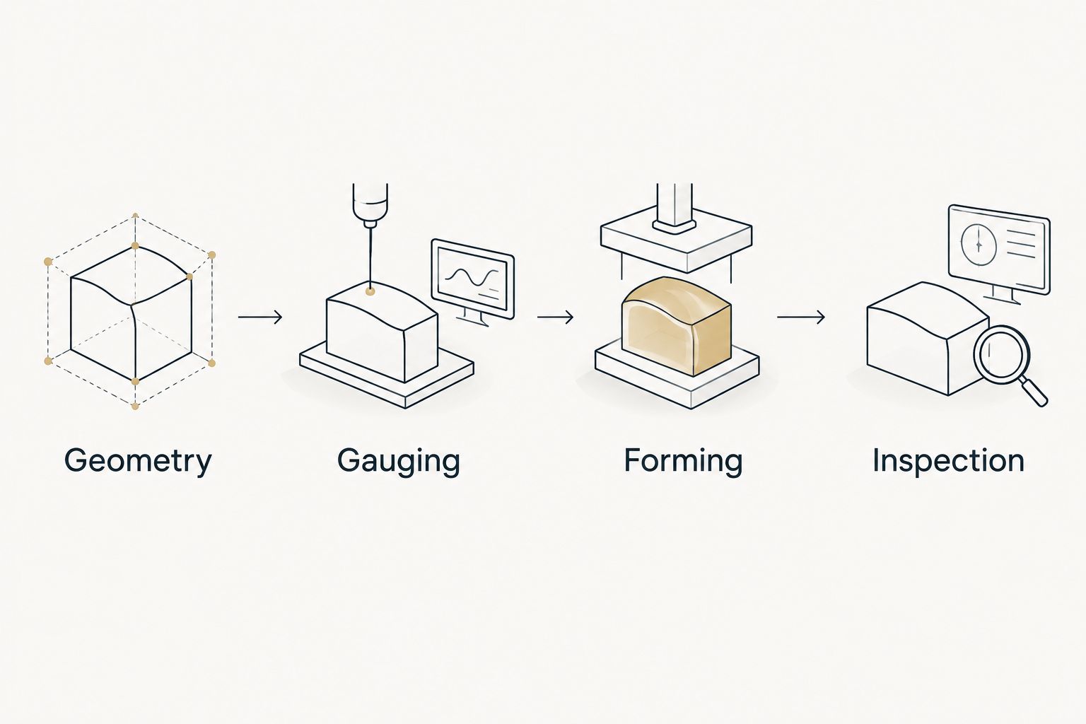
A useful schedule separates Geometry, Gauging, Forming and Inspection. Under those headings, record nominal bend-line locations, programmed positions, forming settings and measured results respectively. Preserve that separation in the 2026 setup record so a later correction does not overwrite the original design intent.
Verify the sequence before forming
Follow the machine manufacturer's setup and safeguarding procedures. Check the programmed sequence, tool identification, support arrangement and collision clearances before conducting the approved trial.
A graphical preview is useful where available, but its accuracy depends on the entered machine, tooling and part data. Do not treat a preview as proof of physical clearance. Verify the actual setup through the machine's approved checking procedure.
Trial forming and release
Correct the cause, not just the final dimension
- Form representative trial material. Use the intended material specification and thickness. Record the actual tool set, setup and material identification.
- Measure local and overall geometry. Check local bend angles, tangent locations, flange dimensions and the curved profile against the drawing's specified inspection method.
- Separate angular error from positional error. A profile with incorrect local angles needs a forming correction; a displaced transition or flange dimension requires review of the layout and gauging references.
- Change one identified variable at a time. Document the reason for each correction and retain the preceding result. Avoid correcting backgauge positions merely to conceal an unresolved springback error.
- Verify repeatability before release. Use the inspection plan required for the job. Record approved settings and measured acceptance results in the 2026 production package.
Expected result: the released program has measured evidence of conformity, not merely agreement with the calculator.
Springback compensation belongs to the verified forming settings. It is not a reason to silently redefine the drawing radius or alter the nominal geometry model.
Recalculate when the drawing or material changes
The adjacent workflow is revision control: update the schedule whenever a drawing, material specification or tooling setup changes. Start from the changed input, not from the last successful correction value.
- Drawing change: review radius, sweep, flange geometry, tangent locations and tolerances; recalculate the affected layout and gauging schedule.
- Material change: review development assumptions, forming loads and springback compensation; validate with representative material.
- Tooling change: review installed height, local radius formation, support, clearance and load limits; repeat the affected setup checks.
Keep the released 2026 program separate from the revised trial version. Preserve both the nominal calculation and the measured corrections so the next setup does not inherit unexplained adjustments.
Troubleshooting
The radius is wrong although the spacing matches
Check the calculator's radius reference first. Inside radius and neutral-line radius describe different surfaces; also inspect local angles and springback before changing the spacing schedule.
The curve looks correct but the flange is displaced
Check the flat-layout datum, tangent transition and gauging surface. Confirm that the operator references the intended edge throughout the sequence and that programmed positions follow the controller's convention.
The end of the curve does not meet the straight flange correctly
Review the end-bend treatment and segmentation convention. Equal internal increments do not, by themselves, establish the required start and finish tangents.
Previously formed bumps interfere with support or gauging
Review the intermediate part shape, tool envelope, support and operation order. Stop the sequence until clearance is verified; changing the finished radius in the calculator does not resolve a physical interference.
Results change across the bend length
Inspect tooling seating, alignment, material consistency and the machine's approved compensation setup. Correct the diagnosed condition and remeasure the profile before editing the nominal geometry.
Customize your workflow
Add controlled worksheet columns for tool identification, clamping interface, installed height, material identification and inspection results. Keep formulas separate from editable inputs, and retain revision history for released schedules.
For custom tools, submit the same controlled input package to Chinacovo rather than sending calculator output alone. The package should connect the finished-part drawing to the machine interface, material and proposed sequence.
If holder compatibility is part of the setup, use the WILA clamping-system connection guide as a separate interface checklist. A verified interface is necessary, but it does not validate bump spacing or springback compensation.
FAQ
What does a bump bend calculator actually calculate?
A bump bend calculator calculates nominal geometry according to its stated inputs and conventions. Check whether its outputs describe arc spacing, chord spacing, bend-line locations or machine-specific positions before using them.
Can I enter calculated offsets directly into my press brake?
Only enter calculated offsets after confirming that their reference matches the controller's backgauge convention. Nominal profile coordinates and physical gauging positions are not automatically equivalent.
Should I enter inside radius or neutral-line radius?
Enter the radius type required by the calculator's documentation. Convert between references using your approved development method rather than treating inside, outside and neutral-line radii as interchangeable.
Are the number of bumps and the number of segments the same?
Bump count and segment count are not automatically the same. Their relationship depends on how the calculation defines intervals and treats the start and finish transitions.
Does adding more bumps guarantee an accurate radius?
No; more segments reduce ideal circle-to-chord deviation but do not guarantee a conforming formed profile. Tool support, local bend radii, springback, clearance and gauging remain separate verification requirements.
How do I compensate for springback during bump bending?
Establish springback compensation through representative trial forming and measured local angles. Keep those corrections in the forming settings rather than silently changing the nominal drawing geometry.
What should I send Chinacovo for a tooling review?
Send the finished-part drawing, machine interface, material grade, thickness, bend length and required geometry. Include installed-height constraints, surface requirements and intermediate shapes that affect clearance.
One last thing
Check the end transitions before refining the middle of the curve. A finely segmented profile can still miss the drawing because its first and last segments join the straight flanges incorrectly. Include tangent conditions in the 2026 release checklist, alongside radius and flange dimensions.
Related guides
- Custom press brake tooling for OEM fabricators
- Bystronic press brake tooling connection guide
- Press brake punches ranked by radius tolerance
Open this COVO engineering guide · Browse press brake tooling · Request technical support