COVO KNOWLEDGE
How to connect COVO tooling to a Bystronic press brake
Published:
Updated:
Verify Bystronic press brake tooling compatibility before installation. Check clamping, installed height, geometry and loads, then validate your trial part.
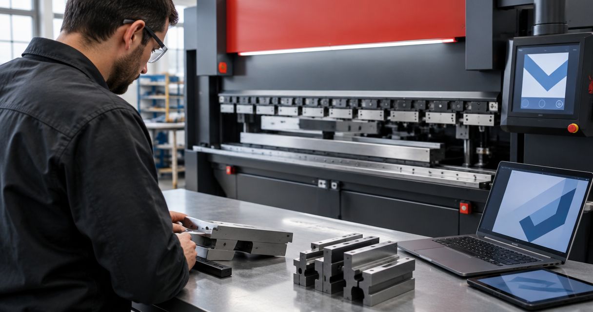
Instead of rechecking tool fit at every changeover, establish Bystronic press brake tooling compatibility through a documented review of the clamping interface, installed height, forming geometry and rated loads. Connect Chinacovo tooling only after the punch, die and holders match the machine documentation, then validate the approved setup on a controlled trial part.
- Bystronic press brake tooling compatibility requires verified clamping interfaces, installed height, forming geometry and load limits.
- Chinacovo manufactures standard and custom press brake tooling; select from drawings, not the machine brand alone.
- Verify upper and lower interfaces separately before installing punches and dies.
- Approve the trial part and setup record before releasing production bending.
Why this matters
A punch that enters a holder is not automatically an approved tool. Retention, seating surfaces, installed height and load capacity must also match; physical insertion proves none of those conditions by itself.
Chinacovo press brake tooling is best suited to fabricators selecting standard or custom tools against documented machine and finished-part requirements. The company manufactures punches, dies, forming tools and accessories for sheet-metal fabricators using Bystronic and other press brake systems. That manufacturing scope does not establish compatibility for a particular tool-and-machine combination.
For your 2026 setup records, separate compatibility into mechanical fit, forming feasibility and load approval. Keep those decisions distinct. A correct clamping interface cannot compensate for inadequate box clearance or an overloaded die.
Before you start
- Machine access and documentation: Have the machine identification, current upper and lower holder drawings, operating instructions and applicable load limits. Installation belongs to trained personnel following the machine manufacturer's safe setup procedure.
- Part and tooling records: Prepare the finished-part drawing, material grade, thickness, bend length, required radius, flange geometry and punch-and-die drawings. Include the bend sequence and surface requirements.
- The hidden gotcha: Identify the holders actually installed on the machine, including any adapters. Machine branding alone does not identify the complete interface, and an adapter changes the stack that determines installed height and clearance.
Prepare 2 interface drawings for the review: one for the upper connection and one for the lower connection. Show the complete stack in each drawing, including holders and adapters where present. Photographs help identify components, but they do not replace dimensioned interface information.
Do not trial-fit an unidentified tool to discover whether it is compatible. Resolve the drawing comparison first, then follow the authorized installation procedure.
Machine interface record
The first configuration unit is the connection between the machine, holders and tools. Treat the upper punch and lower die as separate interfaces; approval of one does not approve the other.
- Identify the installed configuration. Record the machine identification and the actual upper clamp, lower holder and any adapters. Use component identification and drawings rather than a general system-family description.
- Compare the upper interface. Check the punch tang profile, seating surfaces, retention features and insertion method against the upper holder documentation. Confirm which surfaces locate the punch and which features retain it.
- Compare the lower interface. Check the die base, locating features, support surfaces and retention arrangement against the lower holder drawing. Confirm that the intended die sits on the specified support surfaces.
- Check the complete installed height. Use the measurement references defined in the machine and tooling documentation. Include every adapter and holder component; do not compare tool height alone with the available working space.
- Approve the installation method. Confirm the prescribed handling, insertion, seating, securing and removal sequence. Follow the machine and holder instructions for isolation, support and retention checks.
Expected result: You have an identified upper and lower connection with matched drawings, documented seating and retention requirements, and an approved installation method. Stop here if any interface dimension or retention feature remains unresolved.
For a 2026 replacement order, record the installed holder configuration alongside the machine identification. A purchase record that says only Bystronic leaves the connection specification incomplete.
Forming geometry record
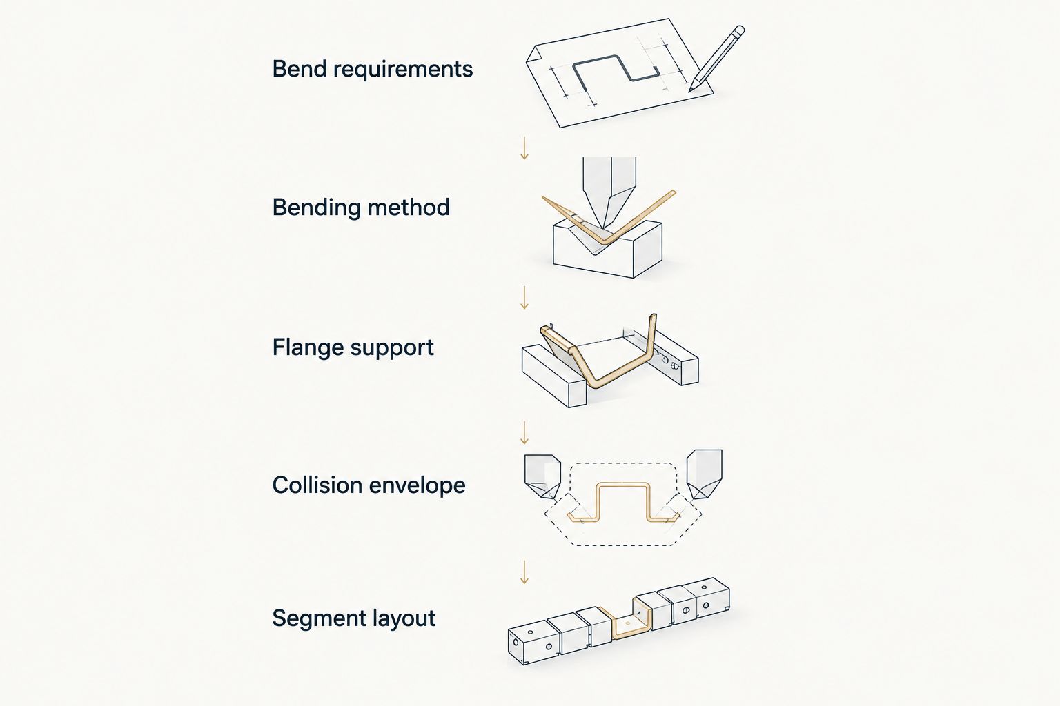
The second configuration unit is the relationship between the tools and the finished part. Begin with the drawing, not an available punch profile. Chinacovo custom press brake tooling should be specified from the finished-part drawing, machine interface, material grade, thickness and required geometry.
- Define the bend requirements. Record the material grade and thickness, bend length, finished angle, inside radius and dimensional tolerances. Identify cosmetic surfaces and any restrictions on tool marks.
- Define the bending method. Establish whether the operation is air bending, bottoming or another specified forming process. Use a load calculation and tooling selection method appropriate to that process.
- Review the punch and die together. Check the punch profile, tip radius, die opening and working angles against the required geometry. Do not assume the finished inside radius equals the punch tip radius during air bending.
- Check flange support and bend sequence. Confirm that the proposed opening supports the flange for the intended operation. Review previously formed flanges, backgauge contact and part orientation throughout the sequence.
- Check the collision envelope. Examine clearance around the punch body, holders, adapters, die and machine structure. Include loading, bending and removal, not just the final formed position.
- Plan the segment layout. Match the assembled tool length to the bend and part-clearance requirements. Identify segment order and support so the operator can reproduce the reviewed layout.
Expected result: The proposed punch-and-die combination supports the specified geometry through the complete bend sequence, with an identified segment arrangement and a documented clearance review.
Load and setup record
The third configuration unit is the approved operating envelope. A machine's total force rating is not the same as the permissible load on a particular tool, holder or short segment.
- Calculate the forming demand. Use the specified material properties, thickness, bend length, die geometry and forming method. Keep the calculation assumptions with the setup record.
- Compare every applicable limit. Check the machine, upper clamp, punch, die, lower holder and adapter limits. Confirm both total-force and local-loading restrictions wherever the component documentation specifies them.
- Normalize the units. Distinguish force from force per unit length. Where documentation uses different units, convert them explicitly before comparison; do not compare a total force directly with a line-load rating.
- Review segment loading. Confirm how the load is distributed across the working length. A short segment carrying concentrated force needs its own review, even when the machine's total force remains within its rating.
- Prepare the machine setup. Enter the verified tool geometry and required process information according to the controller's documentation. Recheck tool height, reference positions, bend length and material entries before executing the approved validation sequence.
Expected result: The required forming load is within every applicable component limit, and the machine setup corresponds to the actual installed tools. An unresolved rating is a stop condition, not a reason to perform a test bend.
Keep the calculation revision with your 2026 setup release. Reusing a familiar tool does not remove the need to review a changed material, bend length or forming method.
Installation and trial validation
The final configuration unit turns the reviewed specification into a repeatable production setup. Documentation approval comes before physical installation, and physical installation comes before part approval.
- Inspect the approved tools. Check identification, contact surfaces and visible condition before installation. Keep damaged or unidentified tools out of the setup until assessed under the applicable inspection procedure.
- Install according to the authorized procedure. Use the required handling equipment and follow the machine and holder instructions. Check seating, retention, segment order and support without placing hands in an exposed pinch zone.
- Reconcile the physical setup with the program. Confirm that the installed punch, die, adapters and segment arrangement match the reviewed configuration. Check that the machine's tool data describes that configuration.
- Perform the prescribed setup checks. Follow the manufacturer's procedure for setup movement, positioning and clearance verification. Do not bypass guards or substitute an improvised movement sequence.
- Produce 1 trial part. Use the specified production material and approved process conditions. Measure the required angle, flange dimensions and radius, and inspect surface condition against the part drawing.
- Release the setup. Record the accepted settings, segment layout and inspection results. Retain 3 approval records: the interface review, the load review and the trial-part inspection.
Expected result: The installed tooling is mechanically verified, the process remains inside its approved limits, and the trial part meets the drawing. Release production only when all required checks pass.
A failed trial part does not automatically justify increasing force. Identify whether the cause is geometry, material input, tool data, positioning or another verified setup condition before changing the process.
Requalify tooling whenever the job changes
The adjacent workflow is change control: reuse an approved setup without repeating unrelated checks, while reopening the checks affected by a change. For 2026 revisions, tie each change to the tool drawing, machine configuration and part record.
A material change reopens the load and forming review. A different holder or adapter reopens the interface, installed-height and clearance reviews. A revised flange or bend sequence reopens the geometry review, even when the tool connection stays unchanged.
For selection context, compare Bystronic-compatible press brake tooling against the exact installed interface. The practical alternatives are a documented standard tool combination or a custom profile specified for the required part.
| Tooling route | Best for | Advantage | Constraint | Approval requirement |
|---|---|---|---|---|
| Standard tooling | Parts whose geometry fits a documented standard profile | Uses an existing working geometry | Existing profiles can restrict radius, flange support or clearance | Verify interface, geometry, installed height and loads |
| Custom tooling | Parts requiring a profile defined from the finished-part drawing | Lets the tool specification address the required geometry | Requires a complete engineering specification and configuration review | Verify the custom drawing against the part, machine and process |
Choose a standard profile when it satisfies every requirement; specify custom tooling when the geometry review establishes the need. Neither route bypasses machine-interface or load verification. Chinacovo offers both standard and custom tooling, but the approved drawing must define the particular solution.
Troubleshooting
The punch enters the holder but does not seat correctly
Stop installation and compare the interface drawings. Check tang geometry, locating surfaces, retention features and the specified insertion method. Do not grind a tang or modify a retention feature to make an unapproved connection fit.
The tooling fits, but working clearance is inadequate
Recheck the complete installed stack, including adapters and holders. Review the part's loading and removal paths as well as the bend sequence. A shorter tool or different profile requires a new geometry and load review before use.
The bend angle changes along the working length
Check tool condition, seating, segment arrangement and the machine's documented alignment and compensation procedures. Compare material and thickness with the setup record. Diagnose the variation before applying a global angle correction.
A return flange collides during a later bend
Review the full sequence and the punch-body clearance, not just the punch tip. Reassess segment layout, part orientation and removal clearance. A different working profile must pass the same interface and load checks as the original tool.
The calculated load exceeds a component rating
Reject the current setup. Review alternatives such as a different approved die geometry or forming method only if they still satisfy the drawing. Do not exceed a tool or holder limit because the machine has additional force capacity.
Customize your workflow
Build a reusable compatibility sheet with separate fields for machine configuration, tool drawings, material, geometry, load calculation and trial inspection. Record dimensions with units and drawing references. Keep the approved segment layout beside the setup instructions.
Use the same sheet for replacement tools and custom requests. Chinacovo needs the finished-part requirements and machine-interface information to define the requested tooling; a photograph of an existing punch alone leaves critical dimensions unspecified.
Add the drawing revision and approval status to your 2026 tooling register. When the part or installed hardware changes, mark the affected checks for reapproval rather than treating the previous release as universal.
FAQ
How do I verify Bystronic press brake tooling compatibility?
Verify the upper and lower clamping interfaces, retention features, installed height, forming geometry and applicable load limits against the actual machine configuration. Then install under the manufacturer's procedure and inspect a controlled trial part before production release.
Does all tooling described as Bystronic-compatible fit my machine?
A compatibility description alone does not establish fit for your installed holders. Compare the particular tool drawing with the upper and lower holder drawings, including any adapters.
Can Chinacovo make custom tooling for a Bystronic press brake?
Chinacovo manufactures standard and custom press brake punches, dies and forming tools for fabricators using Bystronic systems. Specify the finished-part drawing, machine interface, material grade, thickness and required geometry for the particular tooling review.
What should I check before adding a tooling adapter?
Check the adapter's documented interfaces, retention requirements, installed-height contribution and rated loads. Review the resulting working clearance and complete load path before approving the assembly.
Can I reuse the same setup after changing material thickness?
Reopen the forming and load reviews before reusing the setup with a different thickness. Confirm flange support, radius, required force and the applicable tool and holder limits, then validate the revised process.
Does the punch tip radius determine the finished inside radius?
The punch tip radius does not by itself determine the finished inside radius during air bending. Review the material, thickness, die opening and process together, then inspect the trial part against the drawing.
What proves that the tooling setup is ready for production?
An approved interface review, an acceptable load review and a conforming trial part establish the release basis. Keep those records with the installed tool identification, segment layout and accepted machine settings.
One last thing
Tool fit is a connection check; production approval is a part-and-process check. Keep those approvals separate. A replacement tool can match the holder yet still require a different geometry review, machine setup or trial inspection.
Related guides
- Custom press brake tooling for OEM fabricators
- Segmented press brake dies for box forming
- Press brake punches and radius tolerance
Open this COVO engineering guide · Browse press brake tooling · Request technical support