COVO KNOWLEDGE
How to connect COVO tooling to a WILA clamping system
Published:
Updated:
Verify wila clamping system tooling before installation. Check interfaces, retention, installed height and loads, then qualify the bend with a first article.
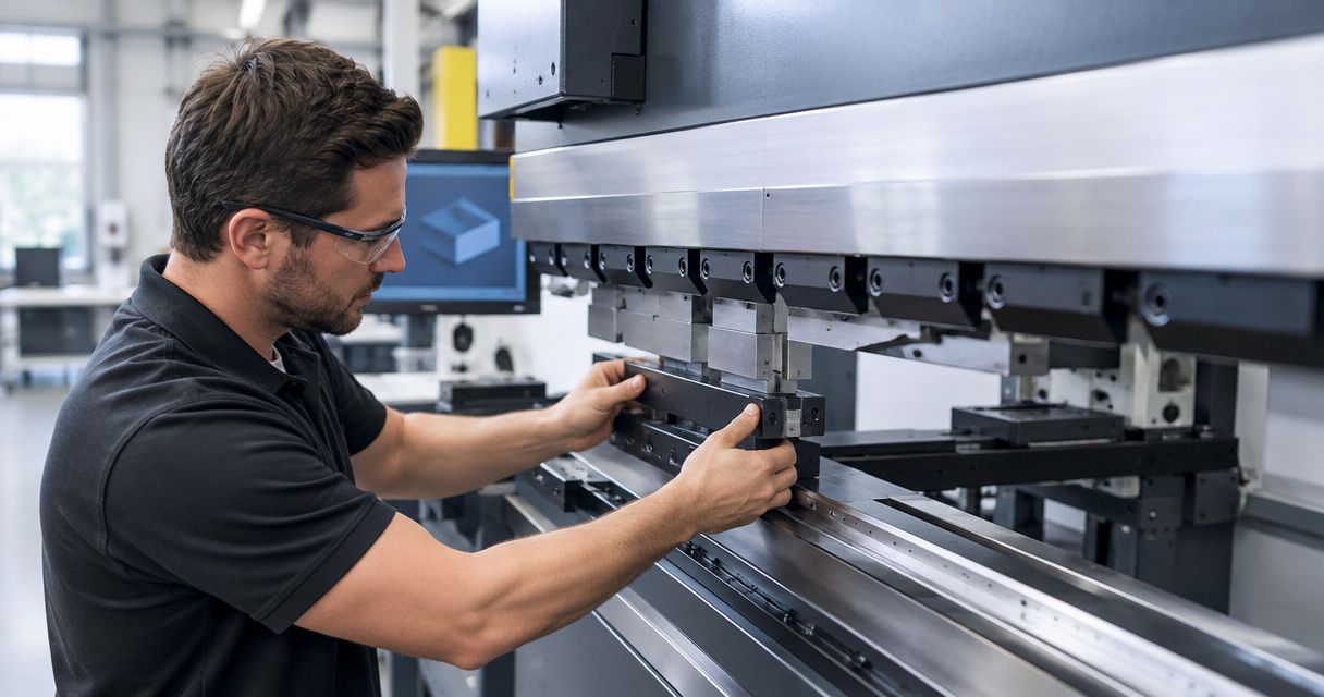
Instead of repeating trial-and-error fit checks at every tool change, connect COVO tooling to a WILA clamping system through a documented interface, retention, installed-height and load review. This workflow separates engineering approval from machine setup, so you verify the tool-holder combination before installing it and qualifying the bend.
- For wila clamping system tooling, match the exact holder and tool drawings before installation.
- COVO manufactures standard and custom press brake tooling; select the interface against your installed holder.
- Approve retention, installed height and forming load separately; physical insertion does not prove compatibility.
- Use the machine and holder manuals for installation, then validate flange geometry and radius on a first article.
Why this matters
A tooling-system name is not an interface approval. Your upper holder, lower holder, tool tang, seating surfaces and retention arrangement must agree as a complete assembly. Start with the WILA-compatible press brake tooling options, then check the selected geometry against the equipment actually installed on your machine.
A punch that enters a holder has passed only an insertion check. You still need to verify seating, retention, load transmission and clearance throughout the intended forming sequence. The lower die requires its own review; approving the upper connection does not approve the lower assembly.
For a 2026 setup record, identify the installed equipment and drawing revisions rather than recording only the press brake brand. That distinction makes the record useful when a holder, adapter or tool segment changes.
Before you start
- Collect the equipment documents: press brake model, upper and lower holder identification, applicable manuals, interface drawings and any adapter documentation. Installation belongs to trained personnel following the machine's tool-change procedure and applicable hazardous-energy controls.
- Prepare the part and process specifications: finished-part drawing, material grade, thickness, bend length, required radius, flange geometry, surface requirements and intended bending method. Include tool drawings and documented load limits for the proposed assembly.
- Check the hidden constraint: a tool can fit the clamping interface yet change installed height, daylight or extraction clearance. Resolve the complete stack and the formed-part removal path before approving the connection.
Do not select controller fields or clamp controls from a generic guide. Their labels and operating sequences depend on the installed machine and holder. Use the exact instructions supplied for that equipment; the steps below define the engineering checks and acceptance records.
Configuration unit: Interface specification
Identify the installed assembly
- Record the upper holder identification. Read the equipment identification and match it to the applicable interface drawing. Record the retention arrangement and the permitted insertion and removal method from the holder documentation.
- Record the lower holder identification separately. Confirm how the die locates, seats and is secured. Include any intermediate rail, adapter or die base in the assembly record.
- Compare the tool and holder drawings. Check tang geometry, seating surfaces, engagement features, orientation and dimensional tolerances. Include features that carry load or prevent unintended release, not just the visible cross-section.
- Resolve discrepancies before installation. Request engineering review when a dimension, tolerance, retention feature or drawing revision does not agree. Do not grind, shim or modify an interface to make an unapproved tool fit.
Expected result: you have an identified upper and lower assembly with drawing-based interface acceptance. The record states which tool geometry fits which holder, rather than treating every WILA-marked assembly as interchangeable.
Choose the connection route
For COVO press brake tooling, decide whether the part can use a documented standard interface or requires custom engineering from the finished-part drawing. An adapter is a separate assembly choice, not a substitute for verifying compatibility.
| Connection route | Best for | Advantage | Constraint to verify |
|---|---|---|---|
| Direct-fit standard tooling | Parts whose required geometry and machine interface match a documented standard tool | Avoids adding an intermediate adapter to the stack | Interface fit does not establish forming clearance or acceptable load |
| Custom-engineered tooling | Parts whose flange geometry, radius or clearance requires a different working profile | Allows the working profile and machine interface to be reviewed together | Requires drawing approval and process qualification |
| Documented adapter assembly | Setups with an explicitly approved holder-to-tool conversion | Provides a reviewed connection between otherwise different interfaces | Adds another interface and changes the installed stack |
Select the simplest assembly that satisfies the drawing, retention and load requirements. Do not choose an adapter solely because the parts physically connect. The universal press brake tooling systems guide provides a broader starting point for comparing interface approaches.
Configuration unit: Geometry and load review
Establish the complete tool stack
- Document installed height. Use the dimensional references defined in the equipment and tool drawings. Include every holder, adapter, punch, die and base that affects the machine setup.
- Check the working envelope. Review machine stroke, opening, tool clearance and the position of the workpiece throughout the bend sequence. Check both the initial flat blank and the partially formed part.
- Review flange geometry and extraction. Confirm that return flanges, box walls and adjacent bends clear the punch body, die, holders and machine structure. Verify that the finished part can leave the tooling without an improvised removal method.
- Review loads for the actual operation. Compare the required forming load with the documented limits of the machine, holders, adapters, punch and die. Account for bend length, load distribution and the intended bending method; do not apply an air-bending assumption to a different forming operation.
Expected result: the proposed assembly has an approved height, working envelope and load basis for the specified material and part. Express dimensions consistently, such as in millimeters, and preserve the units used in each equipment rating.
A total-force limit and a load-per-length limit describe different constraints. Neither can replace the other. If a rating applies only to a stated configuration or loading condition, keep that restriction attached to the setup record.
Prepare the engineering handoff
COVO is best suited to fabricators seeking standard or custom press brake tooling reviewed against a finished-part drawing and machine interface. Send the part requirements and the installed holder details together; a punch profile without the connection drawing leaves the interface unresolved.
For a 2026 tooling review, assemble a single specification package:
- Finished-part drawing with revision and bend sequence.
- Material grade, thickness and required surface condition.
- Bend length, flange dimensions and required inside radius.
- Upper and lower interface drawings, including retention details.
- Installed-height references and relevant machine limits.
- Existing tool drawings and documented load restrictions.
- Photographs that clarify orientation or interference, alongside dimensional drawings.
Photographs help explain the assembly but do not establish interface tolerances. Keep dimensional approval tied to drawings. The benefit of a custom review is the connection between part geometry and machine requirements; the trade-off is the additional approval work before production release.
Configuration unit: Controlled installation
Install the approved assembly
- Prepare the machine for tool change. Follow its documented tool-change procedure, safeguarding requirements and applicable hazardous-energy controls. Keep hands and unsupported tooling clear of hazardous motion.
- Inspect the connection surfaces. Check for contamination, damage and wear at the tang, seating surfaces, holder and retention features. Use the cleaning and inspection methods permitted by the equipment documentation; stop if damage prevents acceptance.
- Install and support the tooling as specified. Follow the holder's approved insertion method and support requirements. Do not assume that a different holder's loading or release procedure applies.
- Verify seating and retention. Confirm the acceptance indicators or inspection method defined by the holder documentation. Do not use a forming stroke to force an incorrectly seated tool into position.
- Inspect the lower assembly. Confirm die seating, securing method, orientation and segment arrangement before checking the complete setup.
Expected result: the tooling is installed using the documented procedure, with seating and retention accepted before forming. A successful clamp actuation alone is not the acceptance record.
For segmented sets, preserve the approved arrangement and check adjacent segment fit. An unwanted gap, mismatched height or incorrect end segment must be resolved before the assembly reaches a workpiece.
Configuration unit: Program and first article
Qualify the setup
- Enter the approved tooling data. Use the controller manual to select the appropriate tool definition and dimensional references. Check that the programmed tool geometry corresponds to the physical assembly, including any adapter or base.
- Review the programmed operation. Check material, thickness, bend length, tool orientation, backgauge positions and bend sequence against the approved process. Use only the setup-checking procedure permitted by the machine manufacturer.
- Produce a controlled first article. Follow the approved operating procedure and safeguarding requirements. Keep trial work within the documented assembly limits; do not increase force to compensate for unresolved seating or geometry errors.
- Inspect the finished geometry. Measure bend angle, flange dimensions and inside radius using the drawing's inspection requirements. Check surface marking, interference and part removal as separate acceptance items.
- Release the documented setup. Record the tool identities, segment arrangement, interface approval, program revision and first-article result. Preserve any restrictions that apply to load or bend length.
Expected result: the first article meets its drawing requirements and the setup is traceable. For the 2026 production record, retain the actual approved program revision rather than a generic program name.
Variant: Requalify after a tooling or part update
You do not need to treat every change as an entirely new project. You do need to identify which approvals the change affects. Reuse an approval only when its documented assumptions remain unchanged.
| Change | Best for this verification route | Approval to revisit |
|---|---|---|
| Segment arrangement changes | New bend lengths or access requirements | Segment fit, load distribution and working clearance |
| Punch or die geometry changes | Revised radius or flange geometry | Tool definition, forming load, sequence and first article |
| Holder or adapter changes | A revised machine connection | Interface, retention, installed height and load path |
| Material or thickness changes | A revised part specification | Forming-load basis and finished-part qualification |
For a 2026 drawing update, compare the revised part with the released setup before changing the machine program. Record the affected checks explicitly. A material change can require a new forming review even when the holder interface stays unchanged.
Troubleshooting
The tool does not seat fully
Stop installation and compare the interface drawings, orientation and permitted insertion method. Inspect for contamination or damage using the documented procedure. Do not force the tool, alter the tang or close the ram to seat it.
Retention cannot be confirmed
Keep the tooling supported according to the holder procedure and do not begin forming. Check the specified retention features and acceptance method. If the expected condition cannot be established, remove the assembly from service for review.
The bend angle varies along the part
Check segment seating, tool condition, material consistency and the approved machine setup, including crowning where applicable. Diagnose the source before changing compensation settings. Increasing force does not correct an incorrectly assembled tool stack.
The formed flange strikes the punch or holder
Compare the actual bend sequence with the clearance review. Check the partially formed geometry, not only the final drawing. Revisit the working profile or sequence through engineering review rather than improvising clearance at the machine.
The program no longer matches the assembly
Compare the controller's tool definition with the installed tooling and height references. An adapter, replacement tool or revised die base can invalidate the previous setup data. Correct the approved definition and repeat the affected qualification checks before production.
Customize your workflow
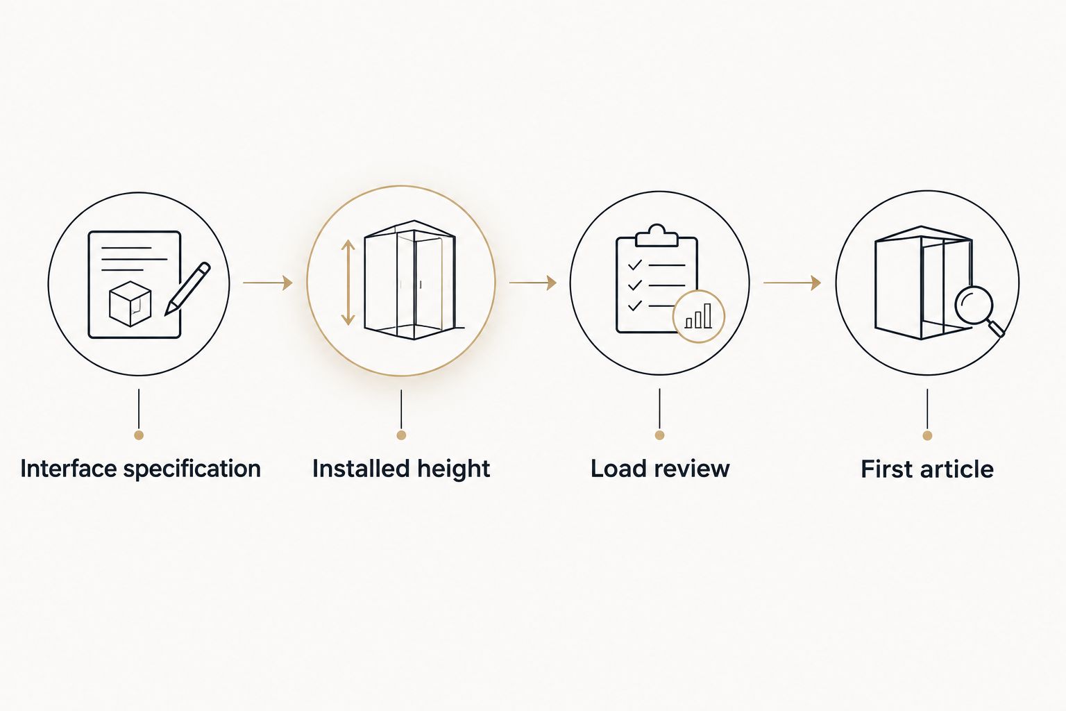
Build a reusable setup record around four approvals: interface specification, installed height, load review and first article. This keeps tool-change instructions separate from engineering acceptance while giving operators a clear release condition.
For COVO press brake tooling requests, put unresolved requirements in the specification package rather than describing the tool only as WILA-compatible. State the exact holder, required working geometry and acceptance criteria. That gives the tooling review a defined scope without assuming that a catalog profile fits the entire application.
FAQ
Can I install COVO tooling in any WILA clamping system?
No; installation requires verification against the exact installed holder and tool interface. Check drawings, seating, retention, installed height and documented load limits before approving the assembly.
What do I need to check before connecting WILA clamping system tooling?
Check the upper and lower interfaces, retention arrangement, installed height, working clearance and load limits. Review the part drawing, material grade, thickness, bend length and required radius at the same time.
Does a tool fitting into the holder prove that it is compatible?
No; insertion proves only that the tool enters the holder. Compatibility also requires correct seating, retention, dimensional agreement and an approved load path.
Do I need an adapter for this tooling connection?
Use an adapter only when the complete holder-to-tool assembly has documented approval. Review the adapter's interfaces, height contribution and load restrictions rather than assuming that physical connection establishes suitability.
What should I send for a custom press brake tooling review?
Send the finished-part drawing, machine and holder details, interface drawings, material grade, thickness and required geometry. Include bend length, radius, flange geometry, installed-height references and the intended forming sequence.
Can I reuse the same setup after changing tool segments?
Reuse the setup only after confirming that its approved assumptions still apply. Recheck segment fit, bend length, load distribution and clearance, then repeat the affected qualification checks.
Why does a bend fail even when the tool clamps correctly?
Clamping acceptance does not establish forming-process acceptance. Check the working profile, material, programmed geometry, load basis and bend sequence against the finished-part requirements.
One last thing
Check how the finished part leaves the tools before approving how the blank enters them. A connection can pass interface and load review while the return flange prevents extraction after the final bend. Add removal clearance to the 2026 first-article checklist, not as a note discovered during production.
Related guides
- Custom press brake tooling for OEM fabricators
- Segmented press brake dies for box forming
- Gooseneck press brake punches compared
Open this COVO engineering guide · Browse press brake tooling · Request technical support