COVO KNOWLEDGE
Can press brake tooling run on hydraulic and servo-electric brakes?
Published:
Updated:
Press brake tooling hydraulic servo-electric compatibility depends on interface, load and clearance. Check drawings and machine limits before moving tools.
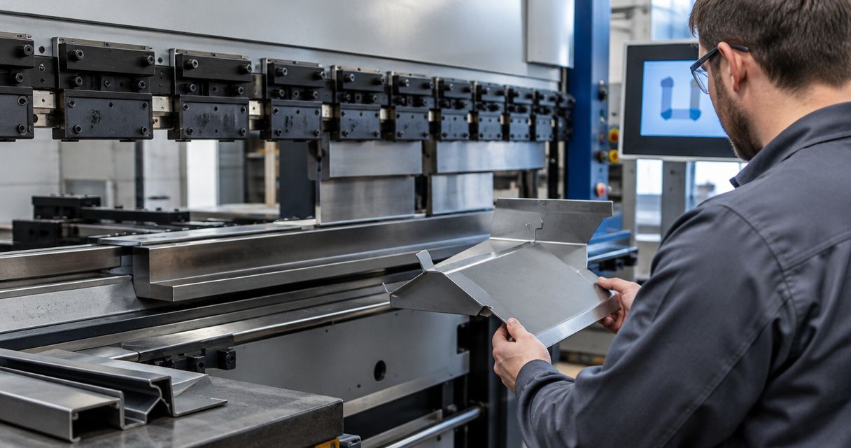
Yes, press brake tooling can run on both hydraulic and servo-electric brakes when the clamping interface, installed height, working geometry and load ratings match the receiving machine. A punch or die fitting into a holder does not establish compatibility: you must also verify retention, available working space, bending force and clearance throughout the bend sequence.
- Press brake tooling hydraulic servo-electric compatibility depends on interface, load and clearance—not the drive system alone.
- Verify punch retention, die seating, installed height and rated loading before transferring tools.
- Chinacovo manufactures standard and custom press brake tooling; custom profiles require part-specific engineering review.
- An existing bend program does not replace setup verification on the receiving machine.
Can press brake tooling run on hydraulic and servo-electric brakes?
Yes. The drive system supplies the ram motion and bending force; the installed holders, tooling interfaces and machine envelope determine whether a particular punch-and-die arrangement fits. Neither hydraulic nor servo-electric actuation establishes a universal tooling standard.
Use the press brake tooling compatibility verification guide alongside the actual machine and tool drawings. A machine-family label is not a substitute for checking the installed holder configuration, especially after clamping-system changes.
| Receiving machine | Best for this tooling decision | Benefit of sharing verified tooling | Constraint to check |
|---|---|---|---|
| Hydraulic press brake | Jobs whose tooling, force requirement and geometry fit the specific hydraulic machine | Reuse of an established punch-and-die arrangement | Actual holder interface, machine loading limits and working envelope |
| Servo-electric press brake | Jobs whose tooling, force requirement and geometry fit the specific servo-electric machine | Reuse of an established punch-and-die arrangement | Actual holder interface, machine loading limits and working envelope |
Approve the tool assembly against the receiving machine, not against the drive-system description. Two machines with different drives can accept the same tooling arrangement; two machines with the same drive type can require different interfaces.
Why this matters
A tooling transfer combines separate engineering questions: whether the assembly mounts correctly, whether it carries the required load and whether it forms the part without interference. Passing one check does not answer the others.
For a 2026 tooling transfer, record the receiving machine's current configuration rather than relying on an old purchase description. Holders, adapters, die bases and control tooling records all belong in the review. Keep the approval tied to the actual assembly and job, not simply to the punch identification.
Verify compatibility before transferring the tooling
Work from the finished-part drawing back to the machine. This prevents a familiar tool profile from becoming the starting assumption when the required radius, flange geometry or bend sequence demands something different.
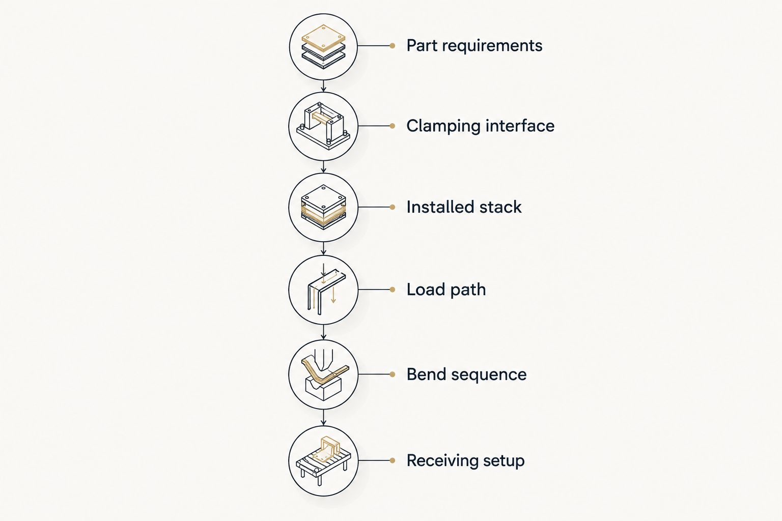
Establish the part requirements
Identify material grade, specified thickness and thickness tolerance, required inside radius, bend angle, bend length and dimensional tolerances. Include surface requirements and the orientation of any features that restrict tool access.
Distinguish the finished inside radius from the punch nose radius. In air bending, the resulting radius depends on the material and die opening as well as the tooling geometry; matching the punch nose alone does not establish the finished result.
Mark short flanges, return flanges, offsets and enclosed features on the drawing. These features determine whether the tool can complete the sequence and whether the finished part can be removed afterward.
Match the clamping interface
Compare the punch tang drawing with the installed upper holder. Verify the seating surfaces, locating features, retention arrangement and permitted insertion method. Then compare the lower die with its holder or die base, including locating and seating details.
Do not treat similar-looking profiles as interchangeable. A tool that enters a clamp can still have an incorrect locating surface or retention feature. Confirm the holder manufacturer's requirements and the tool drawing before attempting installation.
Check interfaces independently at the upper and lower stations. Acceptance of the punch says nothing about the die, and matching the die base does not establish correct upper-tool retention.
Calculate the installed stack
Document the assembled punch height, die height, holders and any adapters. Use the machine manufacturer's dimensional definitions when checking daylight, opening and usable stroke; terminology and reference surfaces must remain consistent throughout the calculation.
An adapter changes the tooling assembly, not just the connection. Its height consumes working space, and its geometry can affect clearance and positioning. Include the adapter in both the physical assembly drawing and the control tooling record.
Check room to load the blank, complete the deepest required movement and remove the finished part. Static fit with the ram open is only the beginning of the clearance review.
Verify the complete load path
Determine the required bending force using a method appropriate to the material, thickness, bend length, die opening and forming process. Air bending, bottoming and hemming do not share an interchangeable force assumption.
Compare that requirement with the documented limits of the machine, punch, die, holders, adapters and support arrangement. Respect both total-force limits and any specified loading-per-length limits. Check the machine manufacturer's restrictions for short bends and off-center loading.
A kN total-force rating and a kN/m tooling rating describe different limits. Keep the units explicit and compare equivalent quantities; do not treat a machine's headline capacity as permission to apply that force to a short tool segment.
Review the bend sequence
Check the part against the punch body, die shoulders, holders, backgauge and machine structure throughout the sequence. Include already-formed flanges and any rotation or repositioning needed between bends.
Review loading and unloading as well as the forming movement. A profile can provide adequate bending clearance yet trap the completed part. Sectional tooling also requires a segment arrangement that permits both forming and extraction.
Use accurate tooling geometry in the programming environment where available. A simplified profile that omits a holder or adapter cannot establish clearance for the complete installed assembly.
Prove the receiving setup
Enter or verify the actual tooling geometry in the receiving machine's control. Reassess bend positions, backgauge movements, opening requirements and the forming sequence rather than copying the previous machine's program unchanged.
Have qualified personnel complete setup and first-piece verification under the machine manufacturer's procedures and the site's safeguarding requirements. Do not bypass retention devices or safeguards to make an unverified tool arrangement operate.
For the 2026 setup record, retain the approved assembly, program revision, material specification and first-piece inspection results together. This gives the next setup a defined reference without implying that a change in material or tooling is automatically covered.
Why hydraulic and servo-electric tooling compatibility varies
Differences between individual machines matter more than a general hydraulic-versus-servo-electric label. Review these factors against the specific equipment and job:
- Installed clamping interface: The upper holder, punch tang, retention system and lower die seating must match. Check replacement holders and retrofits rather than assuming the original configuration remains installed.
- Working envelope: Installed height, available opening and usable stroke must accommodate the tool assembly, blank, formed flanges and part removal.
- Permitted loading: Machine limits, tool ratings, holder ratings and load distribution constrain the usable arrangement. A shorter bend does not justify applying unrestricted machine force.
- Required flange geometry: Punch profile, die opening and bend sequence must support the specified radius and flange geometry without collision or trapped parts.
- Setup and control definition: Tool records must represent the physical tooling. Bend compensation and sequence settings require verification on the receiving machine.
For a 2026 compatibility decision, use these factors as release conditions. An unresolved retention, loading or clearance question is a reason to stop the transfer and obtain the relevant engineering confirmation.
Should you reuse tools, add an adapter or specify custom tooling?
Start with the least complicated assembly that satisfies the part and machine requirements. Do not add an adapter solely because the tool can then be inserted; review the resulting stack height, load path and clearance first.
| Approach | Best for | Advantage | Limitation |
|---|---|---|---|
| Reuse existing tools directly | Verified matching interfaces and suitable part geometry | Avoids adding an interface to the assembly | Existing profile and ratings still limit the job |
| Use a verified adapter arrangement | A documented interface conversion within the machine envelope | Connects otherwise different mounting arrangements | Adds components, installed height and rating checks |
| Specify custom tooling | Required geometry that existing tools cannot produce within verified limits | Allows the working profile to be engineered around the part | Requires drawing-based review; custom geometry does not remove machine limits |
Chinacovo press brake tooling is best for fabricators seeking standard or custom punches and dies reviewed against their part and machine requirements. Chinacovo manufactures these tools, but no custom profile removes the need to verify clamping interface, installed height and allowable loading.
For a custom review, provide the finished-part drawing, receiving machine details, holder drawings, material grade, thickness, bend length, required radius and flange geometry. Identify the current tooling arrangement and explain the specific interference or forming requirement that prevents its use.
Include drawings for both machines if sharing the new tool is a requirement. Approval for one installation does not establish approval for the other, even when both machines are in the same facility.
Can I transfer the same bend program with the tools?
Tool compatibility does not establish program compatibility. The receiving machine needs tooling records and a bend sequence that match its actual holders, installed height, available movements and control requirements.
In a 2026 transfer package, separate the tooling approval from the program release. Retain the same finished-part acceptance criteria, but verify the receiving setup through its own approved process. A successful part from the original brake is a useful reference, not proof of the second setup.
Does a matching tooling-system name prove fit?
A matching tooling-system name is not sufficient evidence of fit. Compare dimensional drawings, seating surfaces, retention features and installed holders before releasing the assembly.
Check the actual mounting arrangement whenever you change machines or holders. The same caution applies when mixing punches and dies from different suppliers: evaluate the complete assembly rather than treating a shared category name as approval.
What should I send before requesting a tooling review?
Send the part drawing and machine-interface information together. A part drawing defines the required result; the machine and holder drawings define the space and interfaces available to achieve it.
Use this checklist for a Chinacovo tooling review:
- Finished-part drawing with revision, bend angles, inside radii and flange dimensions.
- Material grade, specified thickness, thickness tolerance and surface requirements.
- Bend length and proposed forming process for each relevant operation.
- Receiving machine identification and current upper and lower holder drawings.
- Punch, die, adapter and die-base drawings for any components you intend to retain.
- Available opening, usable stroke and applicable machine loading restrictions.
- Proposed bend sequence, clearance concerns and part-removal requirements.
- Requirement to share the tooling between machines, with interface information for each.
Photographs help explain the installed arrangement, but they do not replace dimensioned interface drawings. Identify uncertain dimensions explicitly so the review resolves them before tooling is released for use.
FAQ
Can I use the same punch and die on hydraulic and servo-electric press brakes?
Yes, when both machines accept the tool interfaces and the complete assembly meets their dimensional and loading requirements. Verify each installation separately before use.
Does a servo-electric press brake need special punches and dies?
Servo-electric actuation alone does not define a special punch-and-die interface. Select tooling against the installed holders, machine envelope, allowable loading and part requirements.
Is tooling compatible if the punch fits into the clamp?
No. Physical insertion does not verify seating, retention, installed height, loading capacity or bend clearance.
Can an adapter make my existing press brake tooling compatible?
An adapter can provide an interface conversion when the arrangement is documented and suitable for the machine. Verify its rating, added installed height, retention and effect on clearance before use.
Can I copy the bend program when I move the tooling?
Do not treat a copied bend program as an approved receiving-machine setup. Verify tool geometry, machine movements, bend sequence and first-piece results under the receiving machine's procedures.
What specifications are needed for custom tooling that runs on both machines?
Provide the finished-part drawing, material grade, thickness, bend length, required geometry and interface drawings for both machines. Include holders, adapters, working-space limits and applicable loading restrictions.
One last thing
Check part removal before approving the final bend sequence. A setup that reaches the required angle but traps the finished component has not passed the tooling review.
Make removal clearance an explicit item in your 2026 tooling approval. Review the completed geometry against the punch, die, holders and machine structure—not just against the working tips.
Related guides
- Can press brake tooling interchange between AMADA and TRUMPF?
- Can you mix press brake punches and dies from different brands?
- How to connect tooling to a WILA clamping system
Open this COVO engineering guide · Browse press brake tooling · Request technical support