COVO KNOWLEDGE
Can you mix press brake punches and dies from different brands?
Published:
Updated:
Mix press brake punches and dies from different brands only after checking interfaces, installed height, geometry and loads. Use this verification checklist.
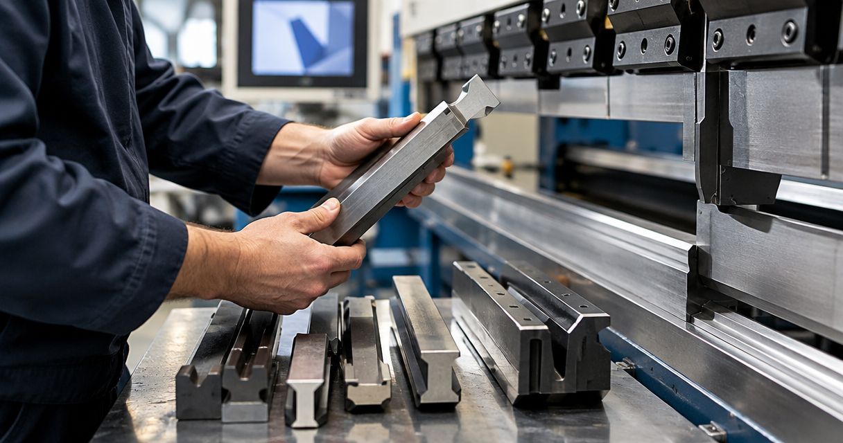
Yes, you can mix press brake punches and dies from different brands when each tool fits its respective holder and the combined setup meets the part geometry, installed height and load requirements. Matching brand names are not a substitute for checking those conditions. A punch that clamps securely and a die that seats correctly still need verification as a working pair.
- To mix press brake punches and dies from different brands, verify clamping interfaces, installed height, geometry and load ratings.
- A matching interface does not establish punch-and-die compatibility for the finished part.
- Check bend length, material grade, thickness, radius and flange geometry before approving the combination.
- COVO manufactures standard and custom press brake tooling; custom selection starts with the finished-part drawing and machine interface.
Can you mix press brake punches and dies from different brands?
Yes, provided the upper and lower tools pass separate mounting checks and a combined forming review. The punch does not need the same mounting interface as the die: each must match the holder that receives it. Their working profiles must then suit the same bend.
For specific interface questions, use the AMADA and TRUMPF tooling interchange guide alongside the actual machine, holder and tool drawings. A system name alone does not establish interchangeability.
| Tooling arrangement | Best for | Advantage | Limitation and required check |
|---|---|---|---|
| Same-brand punch and die | Documented, established setups | Existing records can provide a starting point | Brand identity does not confirm suitability for another material or bend |
| Different-brand tools with matching holder interfaces | Replacing one tool while retaining suitable existing tooling | Allows independent punch and die selection | Verify installed height, working geometry, alignment and individual load ratings |
| Different-brand tools with an adapter | A documented interface conversion | Connects otherwise different mounting arrangements | Review adapter rating, retention, alignment and the changed height stack |
| Custom punch or die paired with an existing tool | Part geometry that existing profiles cannot produce | Addresses a defined clearance or forming requirement | Requires review of the complete pair, not just the custom component |
Approve the documented combination, not the logo on either tool. For a 2026 setup record, identify the exact punch, die, holders and any adapter rather than recording only the manufacturers.
Why this matters
Mixing brands involves more than replacing a worn component. A different punch height changes the setup height; a different die opening changes the forming conditions; a different shoulder profile changes how the sheet contacts the die.
Those changes affect the bend program, part clearance and loading. Keeping the old program unchanged because the replacement looks similar leaves those differences unchecked.
Separate the review into mounting compatibility and forming compatibility. Passing the mounting check lets you evaluate the forming setup; it does not authorize production.
Check the combination before installing it for production
1. Identify the actual clamping interfaces
Record the press brake model, upper holder, lower holder and any intermediate components. Compare the tool manufacturer's interface drawing with the holder documentation, including tang geometry, seating surfaces, locating features and retention arrangement.
Do not treat a broad compatibility description as a dimensional drawing. Inspect the tools for damage, contamination or burrs that prevent proper seating, and follow the machine manufacturer's installation and retention instructions.
The upper and lower mounting checks are independent. A punch fitting the upper clamp says nothing about whether the proposed die fits the lower holder.
2. Verify installed height and machine clearance
Establish the height stack using the dimensional definitions in the relevant drawings. Include the punch, die, holders and adapters, and confirm how the control defines each tool's reference height.
Check the machine's available opening and stroke against that assembled configuration. Include room to load the blank, execute the bend and remove the finished part; completing the downward movement does not prove that unloading is possible.
For a 2026 replacement-tool review, compare the proposed height stack with the approved setup record. Record the difference before changing tool data or program positions.
3. Match working geometry to the drawing
Review punch tip radius and angle together with die opening, included angle and shoulder geometry. Use the material grade, actual thickness, bend length, required inside radius and flange geometry to assess the pair.
In air bending, the resulting radius depends on the material and forming conditions, not simply the punch tip radius. Bottoming and coining require their own geometry and load assessment; an air-bending approval does not transfer automatically.
Check reliefs, return flanges and nearby features through the complete bend sequence. The deepest tool profile is not necessarily the profile that provides clearance where the part needs it.
4. Verify the complete load path
Determine the required forming load using the tooling supplier's or machine manufacturer's applicable method. Compare it with the documented limits of the machine, punch, die, holders and adapters under the proposed loading conditions.
Check the units and scope of every rating. A force-per-length rating is not interchangeable with total permissible force, and a rating for distributed loading does not establish permission for concentrated loading.
Every component in the load path must remain within its applicable limit. If a tool's identity or rating cannot be established, obtain documentation or a qualified assessment before use.
5. Check segments and alignment
For sectional tooling, verify each segment's identity, seating condition, working height and intended position. Equal segment lengths do not prove equal working profiles or height tolerances.
Check punch-to-die alignment across the active bend length using the manufacturer's approved procedure. Do not assume that components from separate sets share a common datum just because they clamp in the same holder.
Short workpieces, interrupted bends and loading near segment ends need specific review. Do not apply a general tool rating without checking its stated loading conditions.
6. Update the setup and validate the bend
Enter the verified geometry and tool data into the control according to the machine documentation. Review the bend sequence, backgauge positions, clearances and required load before making a controlled trial under the shop's approved procedure.
Measure the trial part against the finished-part drawing. Check angle, inside radius, flange dimensions and surface condition, then document any approved adjustments.
A successful trial does not establish the structural rating of an undocumented tool. Validation confirms the part result only after mounting, geometry and load checks have been completed.
Why cross-brand tooling compatibility varies
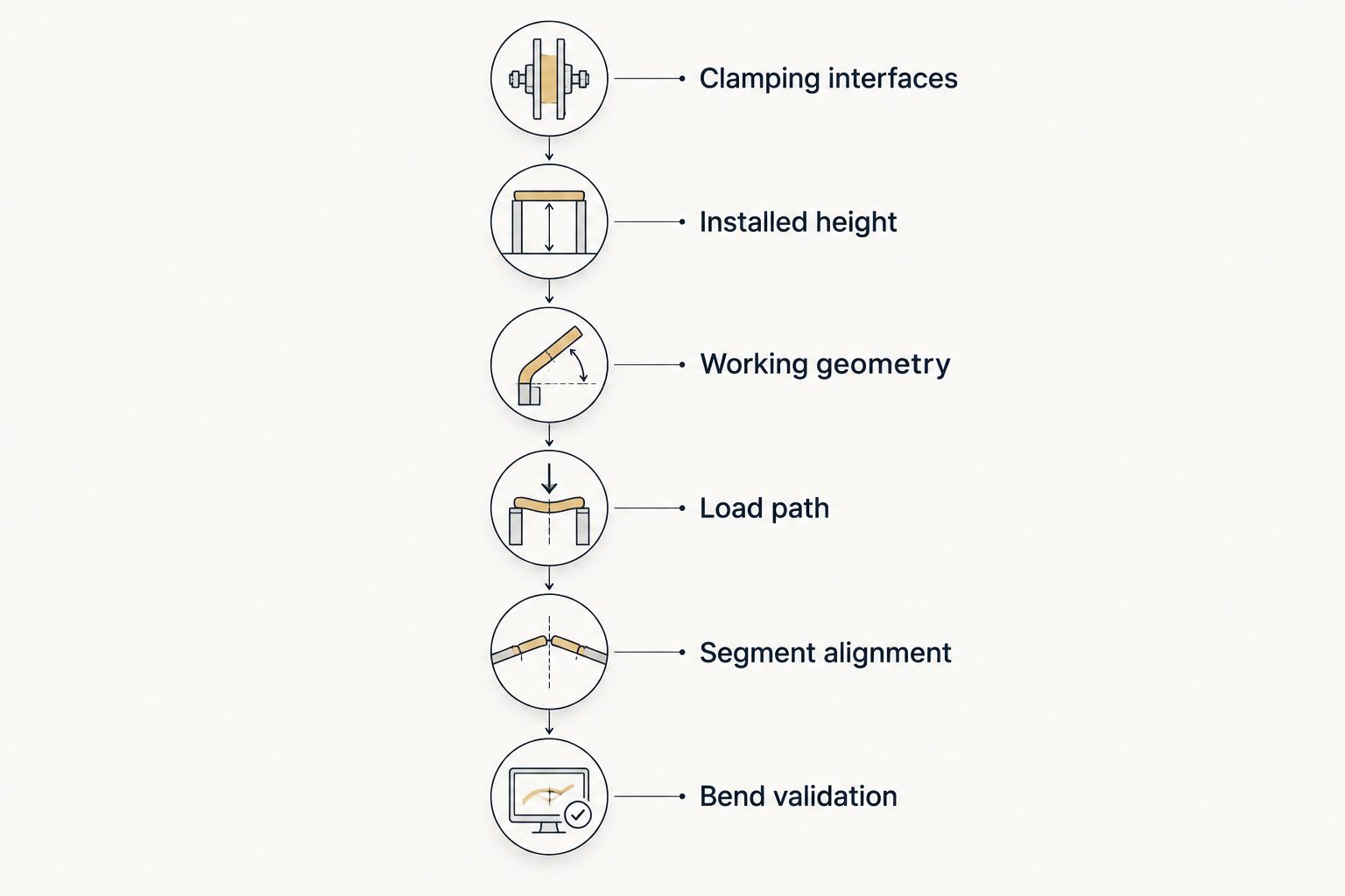
Compatibility changes with the physical setup and the forming operation. Use these factors to explain why a combination approved for one job still needs review for another:
- Clamping interface: Tang dimensions, seating surfaces and retention features determine how each tool connects to its holder.
- Installed height: Tool and adapter heights affect machine opening, stroke requirements and the reference data used by the control.
- Working geometry: Punch radius, tool angles, die opening and shoulder geometry affect sheet contact and the available forming path.
- Material and bend length: Grade, thickness and active bend length influence the required forming load and the resulting bend.
- Part clearance: Return flanges, box walls and bend sequence determine whether the tool clears the part throughout forming and removal.
- Loading arrangement: Segment placement, short bends and off-center work require checks against the applicable tool and machine limits.
Keep these factors in the 2026 setup sheet rather than reducing compatibility to a supplier name. An approved combination is tied to its documented conditions.
Can you use an adapter to mix tooling systems?
Yes, an adapter can connect different mounting arrangements when the adapter is specified for the exact tool and holder combination. An adapter changes the interface; it does not automatically approve the forming setup.
Review the adapter's drawings, retention method, load rating and effect on tool position. Include its height in the assembled stack and check whether it changes the working centerline or available clearance.
An adapter is appropriate when the conversion is documented and the resulting assembly meets the job requirements. Its limitation is the additional interface and dimensional stack that you must verify; it is not a general solution for unidentified tooling.
Can you mix brands within one sectional punch or die set?
Only after checking the segments as a complete assembly. A matching tang and nominal profile do not establish that different segments share the same working height, centerline, angle or radius.
Use a documented matched set where available. If you propose combining segments from different sources, request dimensional and loading review before treating them as one continuous working tool.
Keep segment identification visible in the setup record. Replacing a single segment later is another configuration change, not an automatic like-for-like substitution.
Does the bending method change the compatibility check?
Yes, the bending method changes what the punch and die must do together. Tooling selected for air bending is not automatically suitable for bottoming, coining or a separate hemming operation.
Identify the method before reviewing the pair. Check the required angles, radii, contact conditions and loading for that operation rather than carrying over approval from a different process.
For a 2026 tooling change, record the intended method explicitly. A generic note such as sheet-metal bending does not define the conditions under which the combination was reviewed.
What should you send for a tooling review?
Send a finished-part drawing and enough machine information to reconstruct the proposed setup. Photographs help identify components, but they do not replace dimensioned interface drawings or load documentation.
Use this submission checklist:
- Finished part: Drawing revision, material grade, thickness, bend length, required radius, flange geometry and tolerances.
- Machine and holders: Press brake model, upper and lower clamping interfaces, holder drawings and relevant machine limits.
- Existing tooling: Punch and die drawings, identification marks, installed heights, segment arrangement and documented ratings.
- Proposed change: Which component stays, which changes, and whether an adapter is involved.
- Process requirements: Bending method, bend sequence, surface requirements and any clearance problem the existing setup creates.
- Acceptance criteria: Dimensions and surface conditions that the trial part must meet.
COVO press brake tooling is best suited to fabricators seeking standard or custom tools specified from the finished-part drawing and machine interface. COVO manufactures punches, dies, forming tools and accessories; selection still requires verification of the retained tooling and the complete assembly.
That engineering review is especially relevant when you want to keep a suitable existing die but need a different punch profile. The limitation remains the same: supplying a new component does not establish the condition or rating of the component already in your shop.
FAQ
Can I use a punch and die made by different manufacturers?
Yes, when each tool fits its holder and the assembled pair meets the geometry, clearance and load requirements. Verify the exact tools rather than relying on brand or system names.
Does matching the clamping interface mean the tooling is compatible?
No, matching the clamping interface establishes only part of the mounting check. You must also verify installed height, retention, alignment, working geometry and load limits.
Can I keep my existing die when replacing a punch?
Yes, if the existing die is documented, serviceable and suitable for the proposed punch, material and finished part. Check the complete pair before reusing the previous bend program.
Can I use an adapter with a different brand of press brake tooling?
Yes, when the adapter is specified for the exact tool and holder interfaces and meets the loading requirements. Include the adapter in the height, retention, alignment and clearance checks.
Can I combine different brands of sectional tooling?
Only after verifying the segments as a complete assembly. Check working height, profile, seating, alignment and loading conditions rather than matching segment lengths alone.
Does a successful trial bend prove a mixed-brand setup is safe?
No, a successful trial bend does not establish an undocumented tool's structural rating. Complete the mounting and load review before using a controlled trial to validate part dimensions.
What information does COVO need for a press brake tooling review?
Provide the finished-part drawing, machine and clamping interface information, material grade, thickness, bend length and required geometry. Include drawings and load documentation for any existing tools or adapters you intend to retain.
One last thing
A punch can clear the part at the start of a bend and interfere with it later in the sequence. Check the partially formed part and the removal path, not just the flat blank beneath the punch.
For your next 2026 setup revision, record one complete approved configuration: tool identities, holders, adapters, segment layout, material and bend program. Approve the assembly for the job, not mixed-brand tooling in general.
Related guides
- Connecting tooling to a WILA clamping system
- Minimum flange length by V-die opening
- Segmented press brake dies for box forming
Open this COVO engineering guide · Browse press brake tooling · Request technical support