COVO KNOWLEDGE
Can press brake tooling interchange between Amada and Trumpf?
Published:
Updated:
Are amada trumpf tooling interchangeable? Not automatically. Verify clamping interfaces, retention, installed height, geometry and load limits before transfer.
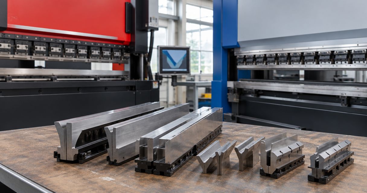
AMADA and TRUMPF press brake tooling is not automatically interchangeable: transfer tools only when the installed clamping interface, retention features, seating surfaces, working geometry and load ratings match. A compatible adapter or replacement holder requires its own verification because it changes the tooling stack, installed height and available clearance.
- AMADA–TRUMPF tooling interchangeability depends on installed holders and tool drawings, not machine names.
- An adapter requires verification of retention, installed height, alignment, clearance and load limits.
- Check punches and dies separately before transferring a complete tooling set.
- COVO manufactures custom press brake tooling for fabricators who need machine-interface and finished-part geometry reviewed together.
Why this matters
A punch that enters a holder has not passed a compatibility review. You still need to establish how the holder seats, retains and supports that punch during the intended bend. Treat insertion, clamping and bending suitability as separate checks.
For a 2026 tooling review, start with the installed holder rather than the machine badge. The AMADA press brake tooling connection guide provides a related starting point for that interface review. Record any replacement clamping equipment or adapters already fitted to the machine; the original machine designation does not describe those changes.
Can press brake tooling interchange between AMADA and TRUMPF?
Only a verified interface match makes tooling interchangeable. The search phrase amada trumpf tooling interchangeable does not describe a single compatibility standard. Determine whether the actual punch, die, holders and machine form a suitable assembly for the intended operation.
Compare the available routes before deciding whether to share tooling between machines:
| Route | Best for | Benefit | Limitation | Required verification |
|---|---|---|---|---|
| Direct transfer | Existing tools with matching installed interfaces | Avoids an additional interface in the stack | Requires matching retention, seating and working geometry | Tool and holder drawings, alignment, installed height and ratings |
| Compatible adapter | Existing tools with a documented adapter solution | Provides an interface transition | Adds stack height and another rated component | Adapter approval, retention, clearance, alignment and load limits |
| Replacement holder | Planned clamping-system changes | Changes the receiving interface | Requires review of the machine-to-holder connection | Mounting, working envelope, tool seating and assembly ratings |
| Dedicated tooling | Parts or machines needing different interfaces | Allows the tooling design to address the specified machine and part | Requires a separate tooling specification and setup | Finished-part drawing, machine interface, material and bend requirements |
Do not choose a route because a catalog uses the same compatibility label on several tools. Match the detailed drawings and ratings. A label identifies a tooling family; it does not establish the condition or configuration of your installed equipment.
Direct transfer: verify the complete interface
Direct transfer is appropriate only when the receiving holder matches the tool's specified connection. Compare the tang profile, locating surfaces, retention features and seating arrangement against the holder documentation. Check the tool's condition as well as its nominal dimensions.
The benefit is a tooling stack without an added adapter. The limitation is that apparent similarity does not establish secure seating or alignment. Reject direct transfer when any interface requirement remains unresolved.
Adapter transfer: verify the revised tooling stack
An adapter is an interface component, not proof that every tool in the source family fits the destination machine. Confirm that the adapter is specified for both connections and for the intended loading. Include it in the installed-height and collision review.
The benefit is an interface transition without replacing the working tool. The trade-off is another seating connection and a changed working envelope. Do not carry over an existing setup program without checking the revised tool position and geometry.
Dedicated tooling: specify the receiving machine
Dedicated tooling is the appropriate route when the required connection or part geometry cannot be satisfied by a documented transfer arrangement. Specify the receiving holder and the finished-part requirements together. A working profile selected without its mounting interface is an incomplete specification.
The benefit is a design tied to the stated machine and part. The limitation is that dedicated tooling does not, by itself, create cross-machine interchangeability. A separate interface review remains necessary before using it elsewhere.
Why AMADA–TRUMPF tooling compatibility varies
Compatibility depends on the installed assembly, not a general comparison of machine brands. Use these factors to structure the review:
- Clamping interface: Match the tool connection to the installed holder, including its locating and seating surfaces.
- Retention features: Verify how the holder retains the tool and whether the specified features engage correctly.
- Installed height: Account for the punch, die, holders and any adapters when checking the machine's working envelope.
- Working geometry: Check punch radius, die opening, tool angles and flange geometry against the finished-part drawing.
- Load limits: Confirm the applicable ratings for the tools, holders, adapters and machine under the intended loading arrangement.
- Segment layout: Verify segment seating, bend length and clearance around returns, sidewalls and previously formed features.
Each factor can prevent transfer independently. A matching punch connection does not correct an unsuitable die opening, and a suitable working profile does not correct an incompatible holder.
Verify the tooling before transferring it
Use the following sequence for a 2026 setup review. Resolve the connection first, then check geometry and loading. Do not use a trial bend to discover whether an undocumented interface is safe.
Machine interface
Identify the receiving press brake and its installed upper and lower holders. Obtain the relevant interface drawings, including any adapter or replacement clamping equipment. Record the mounting arrangement rather than relying on photographs alone.
Compare the tool and holder sections at their functional surfaces. Check where the tool locates, where clamping force acts and which surfaces transmit the bending load. Stop the review if those relationships are unclear.
Tool retention
Verify the specified retention arrangement and loading procedure. Confirm that the tool can seat and engage without modification or forced insertion. Inspect contact surfaces and retention features for damage before assembly.
Do not grind a tang, remove a retention feature or add an improvised shim to make a tool fit. Such changes alter the connection being evaluated. Obtain an approved interface solution instead.
Installed height
Determine the assembled punch and die positions from the actual stack. Include holders and adapters, not just the working tools. Check the resulting arrangement against the machine's opening, stroke and setup requirements.
Installed height also affects part handling and removal. Review clearance with the part in its intermediate shapes, especially where return flanges or enclosed geometry approach the tool body. An acceptable final bend position does not establish clearance throughout the sequence.
Part geometry
Match the working profiles to the material grade, thickness, required radius and flange geometry. Check the die opening and punch profile together. Review the complete bend sequence rather than an isolated cross-section.
Use the finished-part drawing to identify interference risks. Include short flanges, adjacent bends, sidewalls and extraction clearance. A mechanically compatible tool still needs a part-specific geometry review.
Load verification
Check the required bending load against the applicable machine and component ratings. Include the tool, holder and adapter limits, and distinguish total machine capacity from ratings stated for a particular tool length or loading arrangement.
Verify the actual bend length and segment arrangement. Do not extend a rating from one configuration to another without supporting documentation. Record the limiting component and the approved setup conditions.
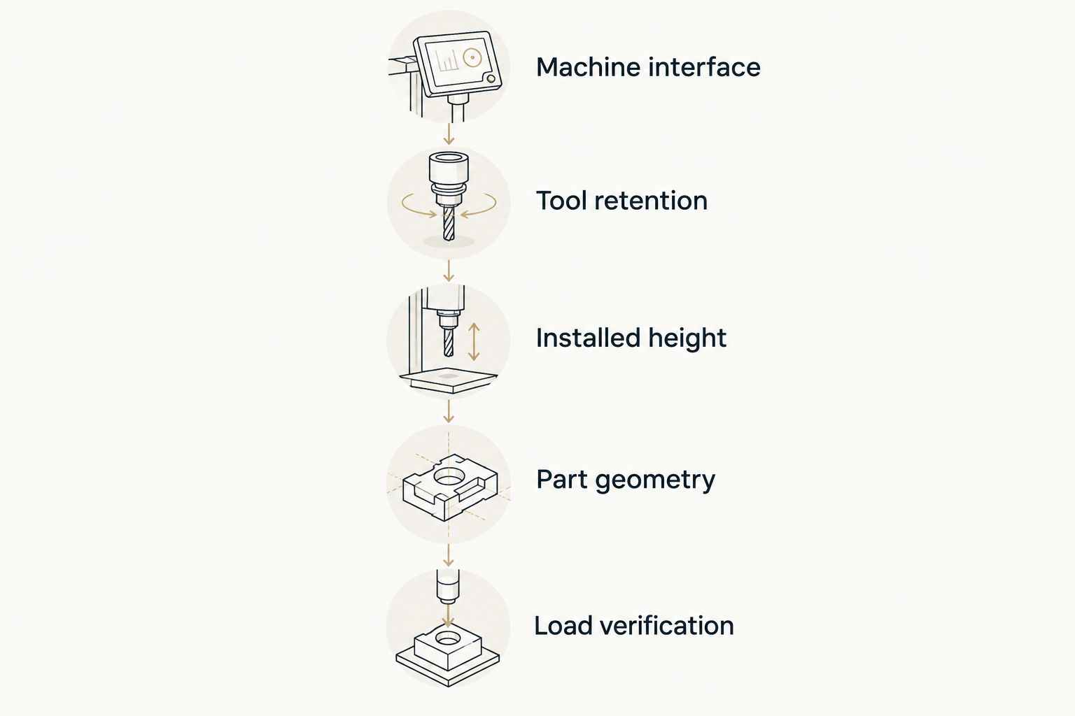
Keep the approved drawing references with the setup record. A 2026 verification should identify the specific tool assembly and intended part, so another operator can distinguish an approved transfer from a visually similar arrangement.
Can an adapter make AMADA tooling fit a TRUMPF press brake?
An adapter can provide a connection only when its documentation covers the actual tool and receiving holder. It does not establish unrestricted interchangeability. Verify both interfaces, the retention arrangement, installed height and assembly load limits before use.
For the receiving-machine checks, consult the TRUMPF press brake tooling connection guide. Use the installed holder specification as the deciding reference, including any modifications to the clamping system.
Can punches and dies be transferred as a complete set?
Punches and dies require separate interface checks before they can be approved as a complete set. Upper-tool compatibility does not establish lower-tool compatibility. After reviewing each connection, verify punch-to-die alignment and the combined working geometry.
Do not assume a transferred set retains the original setup conditions. Differences in holders or adapters change the assembly. Review installed height, part clearance and load limits for the receiving machine.
Does the same bend radius prove tooling compatibility?
The same bend radius does not prove tooling compatibility. Radius describes working geometry, not the clamping interface or retention arrangement. Verify both the mounting connection and the complete punch-and-die combination.
Also distinguish the specified punch radius from the required finished-part radius. The bending method, material and die selection belong in the process review; matching a radius label alone is not a setup approval.
Prepare a tooling review package
COVO press brake tooling is best suited to fabricators who need custom engineering reviewed against both the machine interface and the finished-part drawing. COVO manufactures standard and custom punches, dies, forming tools and accessories for the listed machine systems; that manufacturing scope does not establish that an existing tool transfers unchanged between them.
Send a review package that connects the part requirement to the actual machine setup:
- Finished-part drawing: Include required angles, radius, flange geometry, tolerances and relevant surface requirements.
- Material specification: State the material grade and thickness, with the applicable material information available for load assessment.
- Machine identification: Identify the receiving press brake and its installed clamping equipment.
- Interface drawings: Include the punch connection, upper holder, die base and lower holder details.
- Existing tooling: Supply drawings or identification for the tools you want to retain, including their documented ratings.
- Production setup: State the bend length, segment arrangement, bend sequence and known clearance restrictions.
- Adapter details: Include the connection drawings and ratings for every proposed adapter.
For a 2026 inquiry, identify drawing revisions explicitly. Photos help explain the arrangement, but dimensional drawings and component documentation are needed to define the connection.
Custom tooling requires the same verification discipline as catalog tooling. COVO's custom engineering starts from the finished-part drawing, machine interface, material grade, thickness and required geometry; it is not a substitute for identifying the installed holders correctly.
Prepare your tooling review
Gather the part drawing, holder interfaces, material specification and bend requirements before requesting review.
FAQ
Is AMADA press brake tooling interchangeable with TRUMPF tooling?
AMADA and TRUMPF press brake tooling is not automatically interchangeable. Verify the installed holder interfaces, retention, seating, installed height, working geometry and load ratings before transferring tools.
Can I use an adapter instead of buying dedicated tooling?
An adapter is suitable only when it is documented for the tool and receiving holder. Review both connections, the revised installed height, clearance and assembly load limits before choosing that route.
Does a punch fitting into the clamp mean it is compatible?
A punch entering the clamp does not establish compatibility. Confirm the specified seating, retention and load-bearing surfaces against the tool and holder documentation.
Do I need to check the lower die separately?
The lower die requires a separate compatibility check. Verify its base interface, holder, alignment and rating before reviewing the complete punch-and-die assembly.
Can I keep the same bend program after changing holders?
Do not reuse the bend program without reviewing the revised setup. Holder or adapter changes require verification of tool position, installed height, clearance and the programmed tooling geometry.
What information does COVO need for a custom tooling review?
COVO needs the finished-part drawing, machine interface, material grade, thickness and required geometry for custom engineering. Include holder drawings, bend length, existing tooling details and any proposed adapters.
What should I record when approving a tooling transfer in 2026?
Record the exact tool assembly, interface drawing revisions, ratings and intended part for a 2026 tooling-transfer approval. Include the verified installed height, segment layout and setup conditions so the approval is traceable.
One last thing
Approve the assembly, not the brand pairing. Your setup record should identify the punch, die, holders and adapters together. If any of those components changes, review the affected connection, geometry and ratings before treating the previous approval as applicable.
Keep that rule beside the tooling inventory. It separates a verified cross-machine setup from a tool that merely looks familiar.
Related guides
- Connecting tooling to a WILA clamping system
- Custom press brake tooling for OEM fabricators
- Segmented press brake dies for box forming
Open this COVO engineering guide · Browse press brake tooling · Request technical support