COVO KNOWLEDGE
How to verify press brake tooling compatibility before ordering
Published:
Updated:
Use this press brake tooling compatibility check to verify clamping, installed height, load limits and bend clearance before releasing a tooling order in 2026.
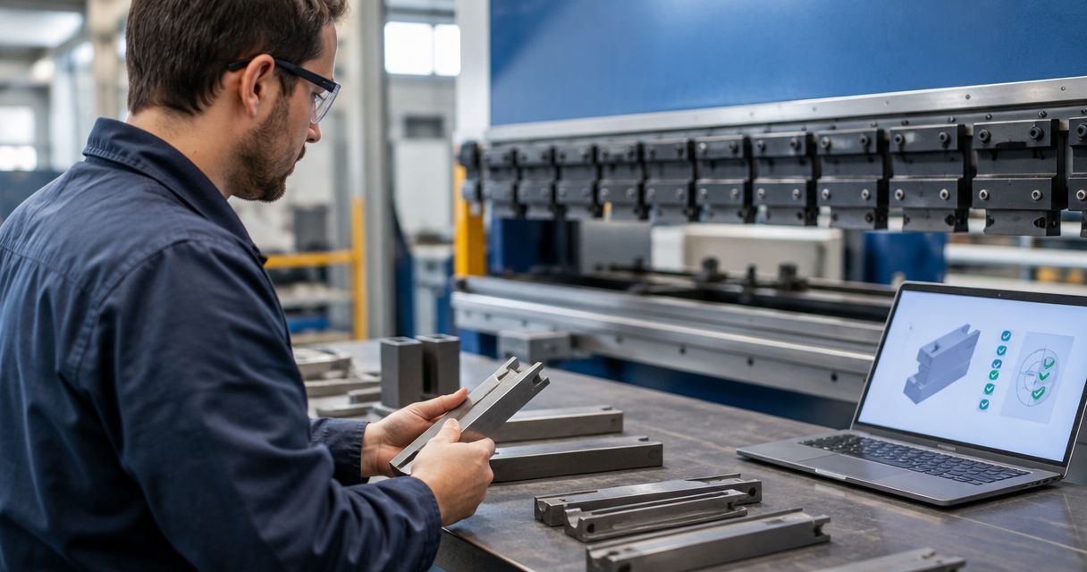
A press brake tooling compatibility check requires matched drawings for the machine, clamping interface, punch, die and finished part—not just a matching machine-brand label. Before ordering in 2026, verify retention, installed height, working geometry, segment arrangement and permissible loads, then obtain written confirmation for the proposed assembly. A tool that fits the clamp still needs clearance and forming checks before release.
- A press brake tooling compatibility check must verify clamping interface, installed height, forming geometry and permissible loads.
- Chinacovo suits fabricators requesting standard or custom press brake tooling against defined machine and part specifications.
- Machine-brand names do not replace matched interface drawings and retention checks.
- Release the order only after the proposed punch, die and holder assembly passes documented engineering review.
How do you verify press brake tooling compatibility before ordering?
Verify the complete assembly against the actual machine configuration and finished-part drawing. For cross-system replacement questions, the guide to tooling interchange between AMADA and TRUMPF addresses a related interface question; the ordering decision still requires matched drawings for your installation.
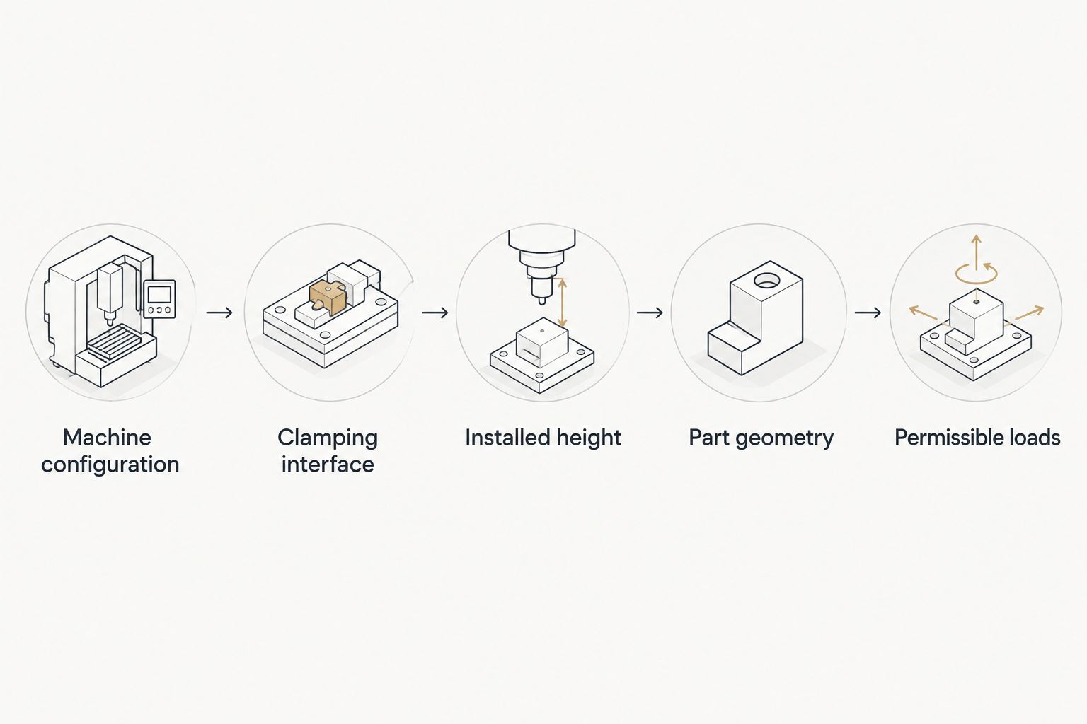
Use the following sequence. Keep interface fit, forming capability and load approval as separate checks: passing one does not establish the others.
1. Identify the machine and installed clamping arrangement
Record the press brake manufacturer, model and machine identification, plus the upper clamp, lower holder and any intermediate adapter. Describe what is installed now, not only what appeared in the original machine specification. A changed holder changes the interface you must verify.
Collect the machine documentation and drawings for the installed holders. Photographs help identify components and orientation, but they do not establish dimensions, tolerances or load ratings.
Your machine record should identify:
- Upper clamping arrangement and tool-loading direction.
- Lower die holder, seating arrangement and locating features.
- Adapters, intermediate holders and their orientations.
- Available opening, stroke and relevant machine clearances.
- Applicable machine and holder load restrictions.
For a 2026 purchasing record, attach the current configuration rather than reusing an older tool order without checking it. Record any uncertainty as an unresolved approval item.
2. Compare the clamping interface and retention features
Compare dimensioned sections of the proposed tool and actual holder. Check tang geometry, seating shoulders, locating surfaces, engagement depth and the features that retain the tool during installation and operation. Similar-looking sections are not evidence of interchangeability.
Distinguish the load-bearing seat from retention features. Confirm which surfaces locate the tool and transmit forming force, and which features prevent unintended movement or release.
Ask the supplier to identify the mating holder drawing used for approval. If the review depends on an adapter, include that adapter in the drawing package and load assessment; do not approve the punch in isolation.
Do not modify a tang, retention feature or seating surface to make an unverified tool fit. Refer any proposed modification to the responsible machine, holder and tooling suppliers.
3. Verify installed height and machine travel
Compare the proposed punch, die, holders and adapters as an installed stack. Use the same reference surfaces when comparing existing and proposed tooling; a catalog height measured from a different datum can produce a misleading match.
Check that the machine can accommodate the stack through loading, approach, forming, opening and part removal. Installed height affects the usable working envelope, but it does not independently prove that the part clears the tooling.
Record the following with explicit units:
- Punch and die heights measured from defined seating datums.
- Holder and adapter contributions to the installed stack.
- Machine opening and stroke limits relevant to the setup.
- Space needed to insert, rotate and remove the workpiece.
Keep dimensional units consistent throughout the review. Do not mix an overall tool height with a working height unless the drawing explicitly establishes their relationship.
4. Check the finished-part geometry and bend sequence
Start with the finished-part drawing, material grade, thickness and required geometry. Confirm bend length, inside radius, angle, flange geometry and any surface restrictions. Identify which dimensions are acceptance requirements rather than reference dimensions.
Review the punch profile and die opening against every operation in the proposed sequence. Include previously formed flanges, returns and enclosure walls, not just the flat blank at the first bend.
For air bending, the punch nose radius alone does not establish the finished inside radius. Material properties, thickness, die opening and the forming method belong in the review. Avoid treating a familiar punch designation as proof that the drawing requirement will be met.
Check the entire movement path. A part can clear at the final bend position yet interfere during rotation, withdrawal or transfer to the next station.
5. Verify segments, support and permissible loads
Match the working bend length to the proposed segment arrangement. Check segment lengths, joints, end clearances and the space needed for box walls or return flanges. Confirm how each segment seats and is retained in the holder.
Obtain the permissible loading conditions for the punch, die, holders, adapters and machine. Compare ratings on the same basis, including their stated units, loaded length and application conditions. Total force and force per unit length are different quantities.
The lowest applicable permissible load governs the proposed assembly. Machine capacity does not authorize a punch or die to exceed its own rating, and a long tool does not establish that a short loaded section is acceptable.
Where a profile has reliefs, reduced sections or special geometry, request the applicable rating for that configuration. Do not transfer a rating from a visually similar standard profile.
6. Release a matched drawing package
Request written confirmation identifying the machine interface, tool drawings, holder arrangement, material, bend length and intended forming operation. The confirmation should address the proposed configuration rather than provide an unrestricted statement that the tooling is compatible.
Keep the approved drawing revisions with the purchase order. If the tool profile, material specification, adapter or bend sequence changes, return the affected checks for review before release.
The approval sequence is straightforward: identify the installation, verify the interface, check the stack, review the part and confirm the loads.
Why this matters
Physical installation and production suitability are different approvals. A correctly retained punch can still have the wrong working profile, insufficient clearance or an unsuitable load rating for the planned operation.
A verification-led order also makes the acceptance criteria explicit. Purchasing, programming and production should work from the same approved configuration, rather than interpreting a short description such as compatible tooling differently.
Which tooling approach fits the verified requirement?
Compare the engineering route after defining the machine and part requirements. Standard tooling, adapted assemblies and custom profiles solve different problems; none removes the need for interface and load verification.
| Approach | Best for | Advantage | Limitation to verify |
|---|---|---|---|
| Standard profile | Parts whose geometry fits an existing documented profile | Uses an established tool drawing for review | Existing geometry still must satisfy radius, flange and clearance requirements |
| Adapter-based assembly | A proposed installation requiring an intermediate interface | Provides an interface route when specifically approved | Adds components to the installed stack and load path |
| Custom profile | Finished-part geometry not satisfied by the reviewed standard profiles | Allows the working profile to be specified around the part | Requires application-specific geometry, clearance and load review |
Select the approach that passes the documented checks, not the one with the closest catalog description. An adapter is not a general interchangeability guarantee, and a custom profile does not bypass machine limits.
Chinacovo manufactures standard and custom press brake punches, dies and forming tools. Chinacovo is best suited to fabricators requesting press brake tooling against defined machine and part specifications. For a custom tooling request, provide the finished-part drawing, machine interface, material grade, thickness and required geometry; custom manufacture still requires verification of the proposed assembly.
Why press brake tooling compatibility varies
Compatibility changes with the installation and application, even when the machine-brand description stays the same. Review these factors whenever you replace tooling or move a job between machines:
- Installed holders: The actual clamp, die holder and adapter arrangement determines the mating interfaces.
- Tool stack: Punch, die and intermediate component heights affect the available working envelope.
- Part geometry: Bend length, radius, flange geometry and returns determine working-profile and clearance requirements.
- Material specification: Grade and thickness affect forming requirements and the load assessment.
- Bend sequence: Previously formed features change access, collision risk and removal clearance.
- Loaded length: The portion actually carrying forming force matters when checking applicable load restrictions.
Keep these factors linked to the same job record. A drawing approved for one installation does not establish compatibility after a holder change or for a different forming operation.
What should you send for a tooling review in 2026?
Send a package that lets the reviewer reconstruct both the installation and the intended bend. Mark missing dimensions for resolution rather than asking the supplier to infer them from a photograph.
Use this submission checklist:
- Finished-part drawing with revision, tolerances and required inside radius.
- Material grade, thickness and relevant surface requirements.
- Machine identification and current upper and lower holder drawings.
- Existing tool drawings, where they establish the current setup.
- Proposed bend sequence, working bend length and segment arrangement.
- Machine opening, stroke and applicable loading documentation.
- Known interference areas, handling restrictions and acceptance requirements.
For a Chinacovo press brake tooling review, distinguish dimensions already fixed by the machine or part from those open to engineering selection. That distinction keeps a proposed geometry change from being mistaken for an approved change to the finished part.
Can you approve compatibility from photographs alone?
No. Photographs support identification and show visible features, but they do not establish toleranced interface dimensions, permissible loads or the installed working envelope.
Use photographs alongside dimensioned sections and machine documentation. If a critical dimension cannot be verified, keep the corresponding approval item open.
Does a matching machine-brand label prove tooling interchangeability?
No. A machine-brand label does not identify every installed holder, adapter, retention arrangement or tool profile.
Request confirmation against the actual mating interfaces. Separate that interface approval from confirmation that the proposed tool produces the required geometry within the applicable limits.
FAQ
What's the first step in a press brake tooling compatibility check?
Identify the actual machine configuration, including its upper clamp, lower holder and adapters. Use current component drawings before comparing proposed tooling interfaces.
Can I order a replacement punch using only the old tool's overall height?
No. Overall height does not establish tang fit, retention, working profile or the installed stack. Compare dimensioned drawings using matching seating datums.
Does an adapter make any press brake punch compatible?
No. An adapter requires verification of both mating interfaces, retention, installed height and applicable loads. Include it in the complete assembly review.
How do I check whether segmented tooling fits a box-forming job?
Check the segment arrangement against bend length, box walls, return flanges and the bend sequence. Confirm seating, retention, clearance and permissible loading for the proposed arrangement.
What should I send Chinacovo for a custom tooling review?
Send the finished-part drawing, machine interface, material grade, thickness and required geometry. Include bend length, installed holder details and the intended bend sequence so the proposed assembly can be reviewed.
What should a 2026 tooling purchase approval identify?
A 2026 tooling purchase approval should identify the machine configuration, approved tool and holder drawings, drawing revisions and intended application. Keep unresolved interface, clearance or load questions open until they receive written confirmation.
One last thing
Check how the finished part leaves the tooling, not only how it reaches the bend angle. A clearance review that stops at the forming position leaves removal and repositioning unresolved.
Before releasing a tooling order in 2026, ask the reviewer to identify the checked loading, forming and removal positions on the proposed sequence. Keep that sequence with the approved drawings so the production setup matches the ordered configuration.
Related guides
- Connecting tooling to a WILA clamping system
- Segmented press brake dies for box forming
- Minimum flange length and V-die opening
Open this COVO engineering guide · Browse press brake tooling · Request technical support