COVO KNOWLEDGE
Minimum flange length benchmarks by V-die opening 2026
Published:
Updated:
Minimum flange length by V-die opening uses a 0.707 × V geometric baseline. Compare calculated values, then verify shoulder support, radius and tooling loads.

For idealized 90° bending geometry, minimum flange length by V-die opening has a geometric baseline of V/√2, approximately 0.707 × V: the illustrative openings below give 4.24–70.71 mm. Use this 2026 reference to screen a drawing—not to approve a bend, because actual minimum flange length depends on die shoulders, material thickness, bend radius and the flange dimension convention.
- Minimum flange length by V-die opening has an idealized 90° geometric baseline of 0.707 × V.
- A 20 mm V opening gives a 14.14 mm geometric baseline, not a production-approved minimum.
- Verify die shoulder geometry, material thickness, bend radius and flange dimension references before accepting a short flange.
- Chinacovo manufactures standard and custom press brake tooling; provide the finished-part drawing and machine interface for review.
Minimum flange length by V-die opening: geometric benchmarks
The table gives calculated geometric baselines, not measured production results or manufacturer-rated minimums. V is the die opening between idealized support points; b is the straight-line distance from the ideal bend apex to the sheet edge at a 90° included angle.
For the accompanying tooling decision, see custom press brake tooling for OEM fabricators. Send the actual tooling section rather than substituting a nominal V opening for the complete die geometry.
| V-die opening, V | Idealized flange baseline, b | Interpretation |
|---|---|---|
| Overall geometric relationship | b/V = 0.7071 | Normalized yardstick; not a production average |
| 6 mm | 4.24 mm | Calculated screening baseline |
| 8 mm | 5.66 mm | Calculated screening baseline |
| 10 mm | 7.07 mm | Calculated screening baseline |
| 12 mm | 8.49 mm | Calculated screening baseline |
| 16 mm | 11.31 mm | Calculated screening baseline |
| 20 mm | 14.14 mm | Calculated screening baseline |
| 24 mm | 16.97 mm | Calculated screening baseline |
| 32 mm | 22.63 mm | Calculated screening baseline |
| 40 mm | 28.28 mm | Calculated screening baseline |
| 50 mm | 35.36 mm | Calculated screening baseline |
| 80 mm | 56.57 mm | Calculated screening baseline |
| 100 mm | 70.71 mm | Calculated screening baseline |
The 6 mm opening has the shortest calculated baseline at 4.24 mm; the 100 mm opening has the longest at 70.71 mm. These are geometric endpoints, not winning and losing tooling choices: a narrower opening reduces this support-distance baseline but increases the force required for otherwise comparable air bending.
Methodology: the 2026 calculations apply the Pythagorean theorem—Euclid, Elements, Book I, Proposition 47, an undated classical geometry source—to a symmetric, zero-thickness, 90° cross-section, with results rounded to hundredths of a millimeter. The model excludes physical shoulder radii, sheet thickness and the curved bend zone, so it cannot establish a tool-rated minimum flange length.
Why this matters
A flange that meets its finished-part dimension still needs support during bending. If the sheet edge loses the required shoulder support, the intended air-bending setup no longer matches the assumed contact geometry.
The 2026 table separates a quick geometric check from the engineering decision. Approve the part against the actual tool section and material specification, not the table alone. A nominal V opening does not describe every contact surface that controls a short flange.
Chinacovo manufactures standard and custom press brake tooling for sheet-metal fabricators who need tooling matched to a finished-part drawing and machine interface. The tooling review must still reconcile the required radius, flange geometry, installed height and load with the proposed setup.
What the geometric benchmark measures
The idealized support triangle
At a symmetric 90° included angle, each straight flange lies at 45° to the die centerline. In the idealized model, the horizontal distance from the centerline to either shoulder support point is V/2.
The flange segment forms the hypotenuse of a right triangle whose horizontal and vertical legs are equal. The Pythagorean relationship therefore gives b = V/√2. This is a geometry calculation, not an empirical tooling rule.
For a 20 mm opening, the horizontal half-span is 10 mm and the resulting inclined length is 14.14 mm. That length describes the ideal apex-to-support distance. It does not automatically equal a finished outside flange dimension, inside flange dimension or flat-pattern length.
The real bend has different reference points
A physical sheet has thickness, and its bend contains a radius rather than a sharp apex. A rounded die shoulder also moves the contact point as the sheet rotates and slides during the stroke.
Consequently, a finished flange dimension cannot be compared directly with the table until you identify its reference surfaces. The 2026 geometric reference uses a deliberately simplified cross-section; the production drawing must use the actual bend geometry.
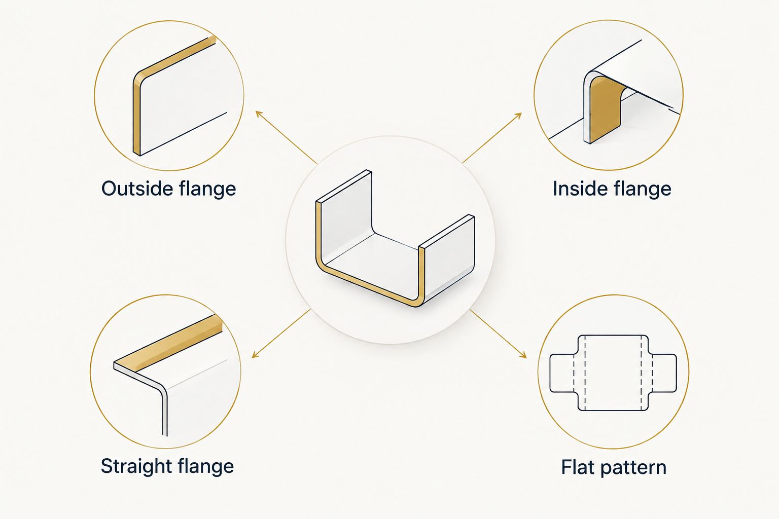
Check these dimension references before calculating clearance:
- Outside flange: identify the outside faces or theoretical sharp intersection used by the drawing.
- Inside flange: identify the inside faces and specified inside radius.
- Straight flange: distinguish the straight segment from the curved bend zone.
- Flat pattern: distinguish developed length from finished-part dimensions.
How to use these benchmarks
Screen the specified flange against the opening
Use the table to identify a geometry question early. For example, the 16 mm opening has an 11.31 mm idealized baseline, while the 24 mm opening has a 16.97 mm baseline. The wider opening requires a longer idealized apex-to-support distance.
If your finished flange approaches that baseline, review the complete cross-section. Do not add an arbitrary allowance and declare the bend acceptable; shoulder geometry, thickness and the dimension reference determine what the comparison means.
Evaluate a smaller opening as a complete setup change
Reducing V reduces the geometric baseline in direct proportion. Changing from 20 mm to 10 mm reduces the calculated value from 14.14 mm to 7.07 mm.
That arithmetic does not approve the smaller die. Recheck bending force, the required inside radius, punch selection, machine capacity and allowable tool loading. A solution to flange support can introduce a load or radius conflict.
Treat the full bend length as a load requirement
The table describes a cross-section, not total bending force. Your setup review also needs the bend length and the tooling manufacturer's applicable load rating.
Verify the machine capacity and the load limits of the punch, die, holders and adapters. For segmented tooling, check the actual segment arrangement and applicable rating rather than assuming a full-length rating covers every assembled configuration.
Escalate geometry conflicts before ordering
When the required flange, radius and opening do not fit together, review the process or tool profile. A different forming approach needs its own contact, clearance and load assessment.
For Chinacovo press brake tooling, provide the finished-part drawing, machine interface, material grade, thickness and required geometry. These inputs define the engineering question more accurately than a request for a smaller V alone.
Compare the available engineering responses
These are process alternatives, not interchangeable tooling specifications. Each response addresses a different constraint, and each introduces a verification requirement.
| Response | Best for | Benefit | Limitation to verify |
|---|---|---|---|
| Retain the current V opening | Parts with verified shoulder support | Preserves the existing setup geometry | The flange must remain supported through the required stroke |
| Reduce the V opening | Short-flange jobs where radius and load permit | Reduces the geometric support-distance baseline | Higher force and changed bend geometry require review |
| Revise flange geometry | Drawings that permit a design change | Adds support without relying solely on a narrower die | Mating features and finished dimensions must still comply |
| Use a dedicated forming tool | Geometry that conflicts with a standard setup | Allows the forming profile to address the specific part | Requires separate interface, clearance and load verification |
| Change the bend sequence | Parts where surrounding features restrict access | Changes when obstructing geometry reaches the tooling | Does not by itself correct insufficient shoulder support |
Choose the response that satisfies flange support, radius, clearance and load together. A narrow die is not automatically the best response, and custom tooling does not remove the need to verify the machine interface.
Chinacovo offers standard and custom punches, dies, forming tools and accessories. Custom engineering is an option for a geometry conflict; it is not evidence that every requested flange can be formed on every machine.
Verification checklist before a tooling review
For a 2026 tooling review, submit one consistent set of drawings and specifications. Conflicting thicknesses, incomplete flange references or an unidentified holder prevent a meaningful comparison between the part and proposed tooling.
Finished-part drawing
- State the flange dimension and its reference surfaces.
- Identify the required bend angle, inside radius and tolerances.
- Show the bend length and all nearby holes, slots, returns and tabs.
- Include the complete part geometry, not only the short-flange detail.
- Identify cosmetic surfaces and permitted contact marks.
Material specification
- State the material grade and actual thickness specification.
- Identify the applicable mechanical-property requirements.
- Record rolling direction relative to the bend where it matters to the process.
- Identify coatings or surface treatments that affect contact requirements.
Tooling section
- Provide the V opening and die shoulder profile.
- Provide the punch angle, tip radius and working profile.
- Identify tool segment lengths and the proposed arrangement.
- Supply the applicable load ratings and their stated conditions.
- Distinguish nominal dimensions from measured or drawing-controlled dimensions.
Machine interface
- Identify the press brake model and clamping interface.
- Provide holder and adapter drawings where they affect fit.
- Verify installed height, available stroke and opening clearance.
- Confirm the applicable machine capacity and setup restrictions.
- Show the intended bend sequence and support arrangement.
Send the matched part, machine and tool information together. A flange dimension without its reference surfaces cannot establish support, and a tool profile without its interface cannot establish machine fit.
Conditions that require a separate benchmark
Angles other than the modeled angle
The 0.707 relationship belongs to the idealized 90° cross-section. Do not apply it unchanged to acute-angle forming or assume the final angle represents every contact condition during the stroke.
Air bending also requires consideration of springback and the deepest forming position. Review support over the intended stroke, not only at the unloaded finished angle.
Bottoming, coining and special forming
Bottoming and coining use different contact and load conditions from the simplified support triangle. Hemming, offset forming and other dedicated operations also need process-specific geometry checks.
Keep their minimum-flange requirements separate from this table. A shared nominal opening does not make two forming processes equivalent.
Features interrupting the bend area
Holes, slots and cutouts can alter the material near the bend and affect the resulting geometry. Nearby returns can also interfere with the punch or die as the part rotates.
A sectional arrangement can address some access constraints, but segment selection does not replace support verification. Check clearance and support as separate requirements.
FAQ
What is the minimum flange length by V-die opening?
For idealized 90° geometry, the flange baseline is V/√2, approximately 0.707 × the V opening. The actual minimum must be checked against the physical die shoulders, material thickness, bend radius and flange dimension reference.
What flange baseline does a 20 mm V die give?
A 20 mm V opening gives a calculated geometric baseline of 14.14 mm in the zero-thickness, symmetric 90° model. That value is not a manufacturer-rated production minimum.
Can I use a smaller V die to bend a shorter flange?
A smaller V opening reduces the geometric support-distance baseline. Before selecting it, verify bending force, required radius, punch geometry and the load limits of the machine and tooling.
Does the table use inside or outside flange dimensions?
The table uses an idealized straight-line distance from the bend apex to the shoulder support point. It is not directly an inside or outside finished flange dimension; reconcile the drawing reference with the actual cross-section first.
Does material thickness change the minimum flange check?
Material thickness must be included in the physical flange-support check. The table excludes thickness, so it cannot establish the minimum for a specific material and tool combination.
Does the same benchmark apply to acute bends and hemming?
No, the 0.707 baseline applies only to the stated idealized 90° geometry. Acute bending, hemming and other forming operations require their own contact, clearance and load assessment.
What should I send Chinacovo for a short-flange tooling review?
Send the finished-part drawing, material grade, thickness, required radius, bend length and flange geometry. Include the machine clamping interface, installed-height constraints, existing tool sections and applicable load ratings.
One last thing
A successful final shape does not prove that the assumed support geometry was correct throughout the stroke. Review the contact path as well as the finished dimension, especially when the edge approaches the shoulder contact zone.
Before releasing a 2026 setup, reconcile the drawing, tool section and approved process information. Keep the geometric baseline on the calculation sheet, but place the verified tool-specific minimum and its dimension reference on the setup documentation.
Related guides
- Minimum bend radius benchmarks by material and thickness
- Press brake tooling for electrical enclosures
- Connecting tooling to a WILA clamping system
Open this COVO engineering guide · Browse press brake tooling · Request technical support