COVO KNOWLEDGE
COVO 3D tooling models to CAD-ready files: 2026 workflow
Published:
Updated:
Prepare press brake tooling 3d models for CAD with checks for units, clamping interface, installed height and revision control before tooling review or setup.
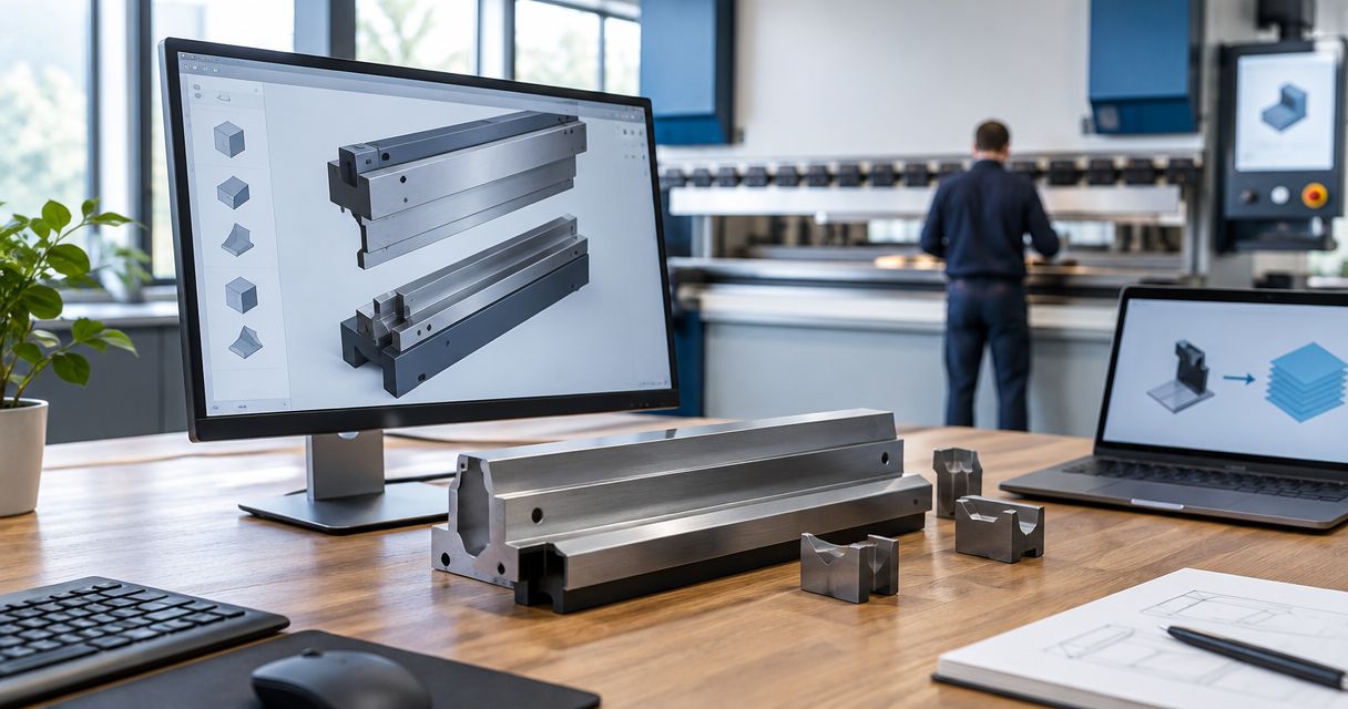
Instead of manually redrawing press brake tooling 3D models for every setup, build a controlled import, interface-check and export workflow that connects the tool geometry to your machine assembly and finished-part drawing. For a 2026 tooling review with COVO, start with the material grade, thickness, bend length and required geometry—not an unverified model downloaded for a similar-looking tool.
- COVO press brake tooling 3D models require drawing, clamping interface and revision checks before CAD release.
- Use solid geometry for dimensional checks; use mesh geometry only for its approved reference purpose.
- Verify installed height, flange geometry and tool clearance in the machine assembly.
- A CAD-ready tooling file does not establish load capacity or authorize a press brake setup.
Why this matters
A tooling model can look correct while representing the wrong tang, segment length or installed height. Those differences affect whether the punch seats in the holder and whether the part clears the tool during the bend sequence. Visual similarity is not an interface check.
COVO manufactures standard and custom press brake tooling for sheet-metal fabricators using AMADA, TRUMPF, WILA, LVD and BYSTRONIC systems. The machine name alone does not define the installed holder, adapters or tooling interface; verify the actual configuration against drawings.
COVO press brake tooling is best for fabricators specifying standard or custom punches, dies and forming tools against finished-part and machine requirements. The CAD workflow supports that specification process. It does not replace an engineering review of forming loads, material behavior or physical setup.
Before you start
- Gather the engineering inputs: finished-part drawing and revision, material grade, thickness, bend length, required radius, flange geometry, surface requirements and proposed bend sequence. Obtain the tooling drawing and a model with an identifiable revision before treating geometry as controlled data.
- Confirm access and machine references: use a CAD system that can import the supplied format, measure geometry and build assemblies. Collect the relevant holder, adapter, die support and machine-envelope drawings, plus the approved method for storing released files.
- Pre-empt the installation gotcha: a tool model without its holder or adapter does not establish installed height. Confirm which components and seating surfaces the model includes before assembling it or setting a reference plane.
For your 2026 file register, record the source, receipt date, drawing revision, model revision, units and intended use. Ask for clarification when the drawing and model disagree. Do not resolve an engineering conflict by editing the imported shape until it looks right.
Source package configuration
The source package establishes what the geometry represents. Keep the original file unchanged, then create a working copy for import and review. This separation lets you distinguish a supplier revision from a local CAD repair.
- Identify the tool. Match the model to the punch, die or forming-tool drawing. Record the profile reference, segment length, clamping interface and any orientation-specific features.
- Define the part requirements. Enter material grade, thickness, bend length, required radius and flange geometry in the review record. Include tolerances that affect tool selection, not just the nominal part shape.
- Define the machine stack. List the upper holder, adapters, punch, lower die and die support included in the assembly. Mark components that are reference envelopes rather than detailed models.
- Request the file purpose. Establish whether the supplied model is intended for dimensional review, collision reference, tool design or another stated use. Request a suitable solid format where dimensional work requires it.
- Separate authority from convenience. Identify the controlling drawing and the source of approved load information. A convenient export is not automatically the controlling engineering document.
Expected result: you have an identifiable tooling package with a stated purpose, a controlling revision and a complete list of required assembly components.
Choose the geometry format by task
The format choice determines what you can inspect and edit. Select from the formats actually supplied or supported by your CAD system; this comparison does not establish which formats COVO provides.
| Format | Best for | Advantage | Limitation |
|---|---|---|---|
| Native CAD file | Editing in the originating CAD system | Can retain application-specific features and assembly relationships | Feature history and relationships depend on how the file was created and saved |
| STEP | Exchanging solid geometry between CAD systems | Supports solid and surface geometry without requiring the original modeling application | Does not guarantee usable feature history or successful translation |
| IGES | Exchanging surface geometry when required | Supports surface and curve exchange | Imported surfaces can require repair before they form a usable solid |
| STL | Mesh-based visualization and envelope reference | Represents surfaces as triangles | Does not retain analytic solid geometry or original feature history |
Use a verified solid model for dimensional tooling review. A mesh can support a visual clearance check, but its tessellation must suit that purpose. Do not treat a triangle edge as the original tool edge or assume a faceted radius is an exact curve.
Import and geometry configuration
Import into a separate review document before placing the tool in a production assembly. Translation errors are easier to isolate when you inspect the tooling body without surrounding machine geometry.
- Set document units. Check the file's declared units and the import configuration. The exact conversion is 1 inch = 25.4 mm; use it to diagnose a unit mismatch, not to invent a missing tool dimension.
- Import the working copy. Select the file format supported by your CAD system. Inspect the translated result before saving it as a native document; menu labels differ by application.
- Measure drawing-defined features. Compare overall length, profile height, tang geometry, punch-tip radius or die-opening geometry with the controlling drawing. Use dimensions that are explicitly defined there.
- Inspect geometry integrity. Check for open surfaces, missing faces, duplicate bodies and unexpected gaps. Use the CAD system's geometry-checking functions where supported, then document any repair.
- Confirm orientation. Identify the bend-length direction, tool centerline and seating datum. Use a consistent coordinate convention across the punch, die and machine references.
- Save the reviewed import. Preserve source identification and revision in the document properties or linked review record. Keep the unmodified source available for comparison.
Expected result: the imported body matches the drawing's dimensions and orientation, and its geometry type supports the intended review.
Do not scale a model merely because it looks too large beside another component. Verify both files' units first. The metric relationship 1 m = 1,000 mm provides another exact check when machine-envelope and tooling files arrive in different units.
Assembly and interface configuration
A correct standalone tool model is only part of the setup. The assembly must represent how the tooling seats, how segments combine and where the workpiece moves. Verify the WILA clamping-system connection separately when that interface is relevant to the machine.
- Locate the seating surfaces. Position the punch and die from their specified machine datums. Do not constrain a tool from a convenient exterior face that is unrelated to its seating reference.
- Check the clamping interface. Compare tang shape, seating geometry and retention features against the holder drawing. Identify adapters explicitly; do not represent an adapter by shifting the tool until the assembly aligns.
- Verify installed height. Measure the assembled stack from the appropriate machine references. Include holders and adapters that change tool position or available working space.
- Build the segment arrangement. Use the proposed segment lengths and positions. Check bend-length coverage, segment joints and box-clearance needs rather than extruding one continuous profile to the overall length.
- Add the workpiece. Place the part at the relevant stage of the bend sequence. Inspect flange geometry, adjacent bends and tool access at each reviewed position.
- Inspect the motion envelope. Check approach, forming and withdrawal positions, including interference with holders, adapters and surrounding machine structure. Record which positions were checked and which remain outside the review.
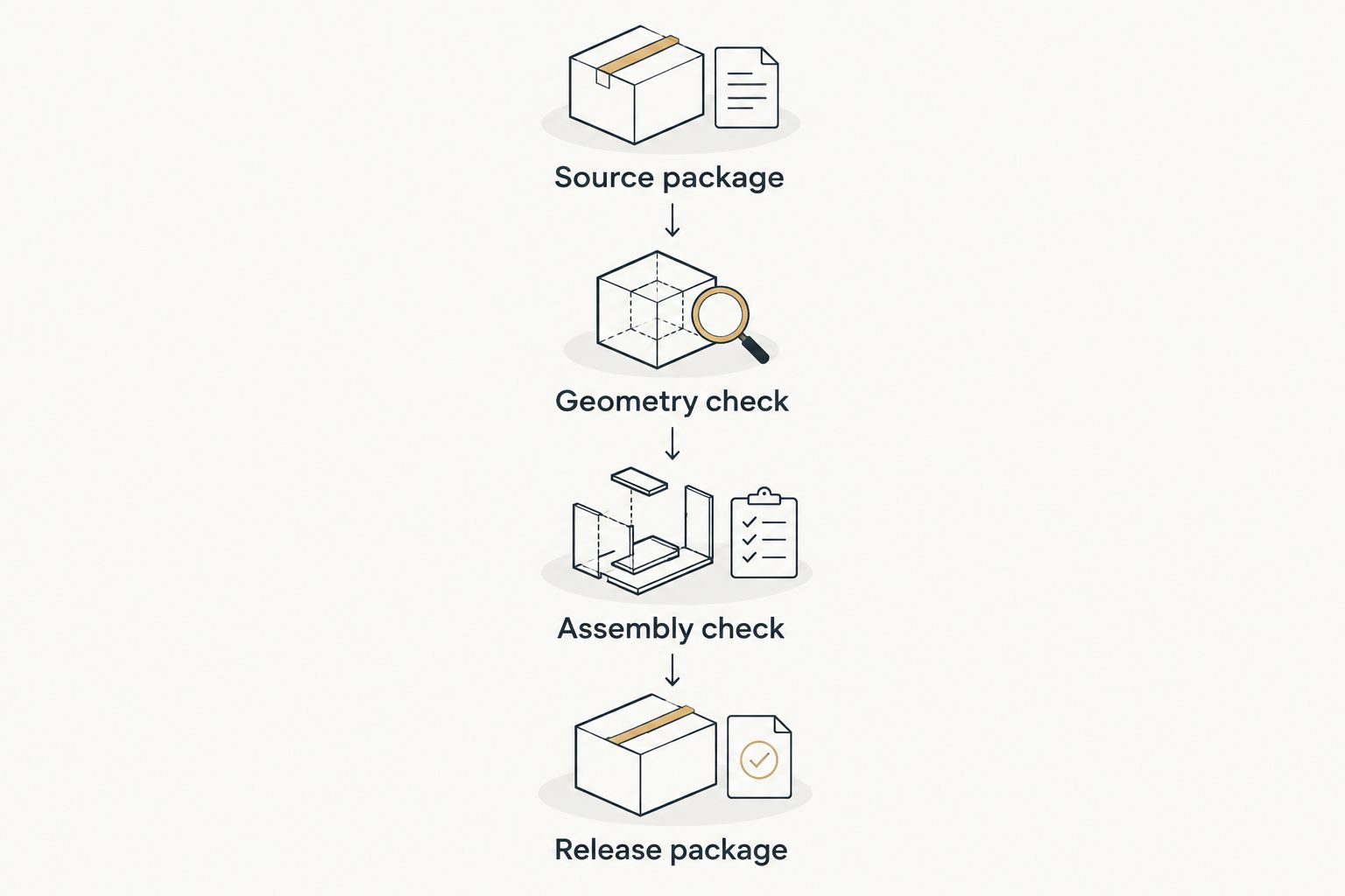
Expected result: the assembly shows the actual proposed tooling stack and identifies clearance conflicts before you release a CAD reference package.
Do not equate clearance with forming capability. A collision-free assembly does not establish permissible load, achievable radius, springback compensation or machine capacity. Compare those requirements with approved tooling and machine information outside the geometric check.
For a 2026 release, keep the assembly review tied to the specific machine configuration. Reusing the same punch on another press brake requires another interface and installed-height check, even when the machine uses the same named tooling system.
Export and release configuration
A CAD-ready file is suitable for a defined downstream task. Define that task before export: dimensional review, machine-envelope reference and tooling design do not require identical information.
- Select the export scope. Include the intended tool bodies and reference geometry. Exclude unrelated components, but retain any holder or adapter needed to interpret installed position.
- Choose the recipient format. Confirm the receiving system's supported format and geometry requirements. Export a solid exchange file for a solid-based review; do not substitute a mesh without agreement.
- Preserve identity. Associate the export with the tool reference, source revision, local review status and units. Keep assembly position information when the receiving task requires it.
- Reopen the exported file. Import it into a fresh document and repeat the critical dimension and orientation checks. Inspect the exported artifact, not just the native file that produced it.
- Package the engineering context. Include the controlling drawing, review record, machine-interface references and stated limitations. Carry approved load information separately rather than implying it from geometry.
Expected result: the recipient receives a traceable file that reopens correctly and states what has—and has not—been verified.
COVO custom tooling review should start from the finished-part drawing, machine interface, material grade, thickness and required geometry. A CAD assembly helps explain those requirements, but supplying it without the specifications leaves the engineering request incomplete.
Revalidate whenever the tool or part is updated
Use the same workflow for a revision rather than overwriting the previous released file. A changed tool profile can affect clearance; a changed part flange can affect bend sequence even when the tooling model remains unchanged.
- Identify the changed drawing, model or machine component and preserve the previous release.
- Compare the changed geometry with the last reviewed package. Highlight differences in tang, radius, profile height, segment length or flange geometry.
- Repeat affected import, interface, installed-height and clearance checks. Recheck export integrity when you generate a replacement file.
- Issue the revised package with its review status and identify the superseded files.
Expected result: the updated package has its own traceable review, and the previous approval is not silently applied to changed geometry.
Keep your 2026 revision register linked to the finished-part revision as well as the tooling revision. This prevents an unchanged tool file from being mistaken for approval of a newly changed part.
Troubleshooting
The tool imports at the wrong size
Check source units, document units and import settings before changing geometry. Measure a dimension from the controlling drawing. Correct the import interpretation and repeat the check; do not leave an unexplained scale operation in the released model.
The punch floats above the holder or seats incorrectly
Check the assembly datum, tang geometry and adapter representation. Remove constraints based on unrelated faces and rebuild the seating relationship from the interface drawing. If the drawings conflict, resolve the interface before proceeding.
The imported body contains surfaces instead of a solid
Inspect missing faces, gaps and translation warnings. Request another suitable export or perform documented repair in a working copy. Repeat dimensional checks after repair, especially where the repaired geometry affects radius or contact surfaces.
The tool clears the flat blank but collides later
Review the intermediate workpiece shapes and bend sequence. Add formed flanges, segment ends, holders and adapters to the relevant positions. Flat-blank clearance does not establish clearance after adjacent bends are formed.
The export opens but loses useful assembly information
Check whether the chosen format and export scope preserve the required bodies and positions. Reopen the file in a fresh document, then compare its contents with the release checklist. Supply an assembly reference drawing when the recipient needs positioning context.
Customize your workflow
Extend the verified model into a tooling library organized by clamping interface, working profile, installed height and segment arrangement. Separate released entries from preliminary or visualization-only files so engineers do not select an unreviewed model by appearance.
For repeated parts, link each reviewed tooling assembly to its material specification and bend sequence. Record the limits of the review: geometry approval for one part does not establish suitability for a different material, bend length or forming operation.
Prioritize traceability over file quantity. One verified assembly with its drawings is more useful than a folder of similar profiles without revisions. Make the 2026 library release checklist require source identity, dimensional checks, interface checks and export verification.
FAQ
How do I prepare press brake tooling 3D models for CAD?
Verify the source drawing and revision, import with the correct units, inspect geometry, and check the tooling in its machine assembly. Reopen the exported file before releasing it for a defined downstream task.
Which CAD format is best for press brake tooling models?
STEP is suitable for solid-geometry exchange when both CAD systems support it. Native CAD files suit editing in the originating system, while STL is a mesh format rather than a replacement for analytic solid geometry.
Can I assume COVO provides a downloadable model for every tool?
Do not assume model availability or format for a specific tool. Request the geometry required for your review and identify the finished-part drawing, machine interface and tooling reference.
Does a 3D tooling model prove the punch fits my press brake?
No; fit requires checking the clamping interface, seating surfaces, retention features, adapters and installed height against the actual machine configuration. A similar-looking tool profile is not sufficient evidence.
Can I use an STL file to check a punch radius?
Do not use an STL file as the controlling source for an exact punch radius. Confirm the radius from the tooling drawing and suitable geometry because STL represents surfaces with triangles.
Does a collision-free CAD assembly confirm safe bending loads?
No; a collision-free assembly verifies only the geometric conditions reviewed. Confirm forming loads and permissible tooling and machine loads from approved engineering information before setup.
What should I send for a custom tooling review?
Send the finished-part drawing, material grade, thickness, bend length, required radius, flange geometry and machine-interface information. Include the proposed tooling assembly and revisions where available, with unresolved clearance or installation questions identified.
One last thing
The file that needs verification is the exported file your colleague receives. A correct native assembly does not prove that its translated copy retains the intended bodies, units or positions. Reopen the delivered artifact and check it before marking the package released.
Related guides
- AMADA press brake connection checks
- Segmented press brake dies for box forming
- Custom press brake tooling for OEM fabricators
Open this COVO engineering guide · Browse press brake tooling · Request technical support