COVO KNOWLEDGE
How to connect COVO tooling to an Amada press brake
Published:
Updated:
AMADA press brake tooling compatibility requires verified fit, height and load limits. Check COVO tooling interfaces, geometry and first-off parts before release.
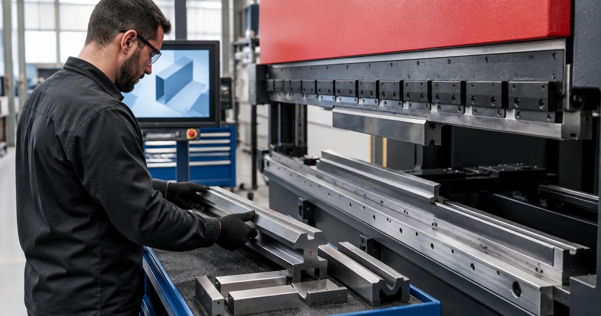
Instead of checking punch fit by trial installation, verify AMADA press brake tooling compatibility through the clamping interface, installed height, working geometry and rated load before mounting COVO tooling from Chinacovo. Use the workflow below to turn machine records and a finished-part drawing into a controlled tooling setup.
- AMADA press brake tooling compatibility requires verified interfaces, installed height, working geometry and load limits—not a matching brand label.
- Chinacovo manufactures standard and custom press brake tooling for fabricators using AMADA systems; confirm the actual holder configuration.
- Check punch retention and lower die seating separately before approving a matched tooling assembly.
- Release the setup only after documented clearance checks and an inspected first-off part.
Why this matters
An AMADA machine name does not identify every component currently installed on the press brake. Replacement holders, intermediate clamps and lower die holders affect the interface that the tooling must actually fit. Start with the installed assembly, not a catalog description.
A punch that enters a holder has not passed a compatibility check. Retention, seating, installed height and load capacity remain separate requirements. The working profile must also produce the specified radius and flange geometry without colliding with previously formed features.
Use the AMADA-compatible press brake tooling guide as background, then verify the selected tools against your machine documentation. Chinacovo is best suited to fabricators seeking standard or custom press brake tooling reviewed against their machine interface and finished-part geometry.
For a 2026 setup record, keep interface approval separate from process approval. Mechanical fit establishes whether the assembly can be mounted correctly; process verification establishes whether it can make the required part within approved operating limits.
Before you start
- Machine access and documentation: Obtain the exact machine model, operating manual, installed upper clamp and lower holder identification, and their dimensioned interface drawings. A qualified operator must control installation and commissioning under the machine's safety procedures.
- Part and material records: Prepare the finished-part drawing, material grade, thickness, bend length, required inside radius, flange dimensions, bend sequence and acceptance tolerances. Include the proposed punch and die drawings with their stated load ratings.
- The hidden mismatch: Identify every intermediate clamp, adapter and holder already fitted. These components alter the tool stack; checking only the punch tang leaves installed height, seating and alignment unresolved.
Do not proceed with mounting when the interface drawing, retention method or applicable load rating is unresolved. Send the open questions for engineering review first. Physical installation is not a substitute for missing specifications.
Machine interface record
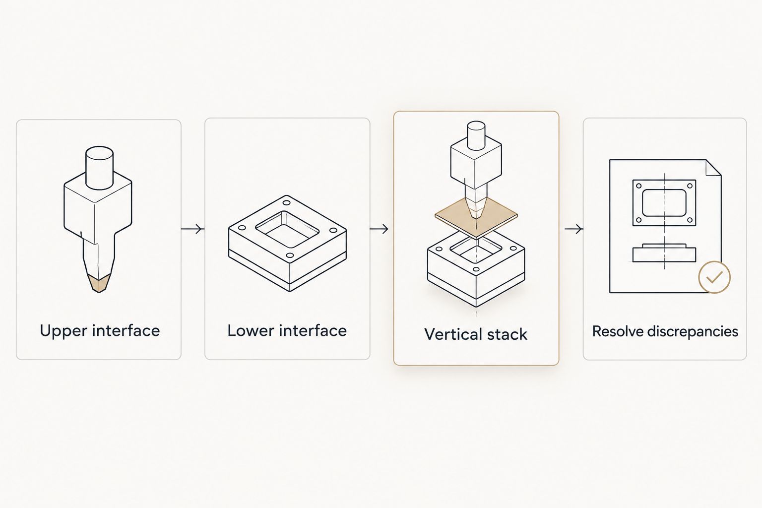
- Identify the installed assembly. Record the machine model and the identification of the upper clamp, intermediate components and lower die holder. Photograph the interfaces as supporting evidence, without treating photographs as dimensional approval.
- Record the upper interface. Compare tang geometry, seating surfaces, insertion method and retention features with the proposed punch drawing. Check the complete interface rather than selecting one matching dimension.
- Record the lower interface. Compare the die base, locating features, support surfaces and holder engagement with the lower tooling drawing. Confirm the prescribed method for locating and securing the die.
- Establish the vertical stack. Record punch height, intermediate component height, die height and the relevant holder reference dimensions. Use the machine manufacturer's definitions for installed height and tooling reference positions.
- Resolve discrepancies. Mark each mismatch on the drawing and obtain an approved resolution. Do not grind a tang, remove a retention feature or add improvised packing to make an unverified tool fit.
Expected result: A documented upper and lower interface match, with the complete installed height identified and no unresolved seating or retention questions.
Keep the record in consistent units. State dimensional values in mm or inches and copy load ratings with their original units and rating basis. A total-force rating and a force-per-length rating are not interchangeable entries.
Controller labels differ between machines and control versions. Use the exact tool-definition fields and setup procedures in your machine manual; do not transfer field names or height conventions from an unrelated press brake.
Tooling geometry and load review
- Select the bending method. Specify air bending, bottoming or another intended forming operation before checking the tooling. Do not transfer a force calculation or tool approval between methods without review.
- Match the working profile. Review punch tip radius, punch angle, die opening, die angle and shoulder geometry against the material and required finished bend. In air bending, punch tip radius alone does not establish the finished inside radius.
- Check flange support. Verify that the planned flange geometry can be formed and supported with the chosen die opening. Include holes, cutouts and narrow features near the bend that affect support or deformation.
- Check bend sequence clearance. Examine the part throughout approach, forming and withdrawal. Include return flanges, box walls, backgauge fingers, holders and intermediate components in the clearance review.
- Check load limits. Calculate the required force using an approved method for the material, thickness, bend length and forming operation. Compare it with the applicable machine, clamp, holder, punch and die limits, including restrictions on concentrated or off-center loading.
- Check sectional arrangements. Verify segment lengths, joint locations, retention and working-height consistency. Review the shortest loaded tooling sections rather than assuming a full-length capacity applies to every arrangement.
Expected result: A tooling assembly that matches the part geometry and has a documented load assessment for the actual bend location and active bend length.
Which tooling route fits the job?
The following routes describe engineering choices, not interchangeable assemblies. Select the route only after the interface record and part review establish what must change.
| Tooling route | Best for | Advantage | Limitation and required check |
|---|---|---|---|
| Standard tooling with a verified matching interface | Parts whose radius, flange geometry and clearance fit an existing working profile | Keeps the assembly within a defined tooling geometry | Interface fit does not prove part clearance or forming suitability |
| Custom punch or die | Finished-part geometry that an existing profile cannot accommodate | Allows the working profile to be specified from the drawing | Requires review of the custom section, retention, installed height and load rating |
| Approved adapter assembly | A documented interface conversion permitted for the machine and holders | Provides a defined connection between otherwise different interfaces | Changes the stack and requires assembly-specific approval; it is not a fit workaround |
Choose standard tooling when the complete assembly passes review; request custom engineering when the finished-part geometry demands a different profile. Chinacovo manufactures both standard and custom press brake tooling, but that does not establish approval for any particular machine configuration.
For a custom request, use the custom press brake tooling guide for OEM fabricators to organize the drawing package. Include the machine interface, material grade, thickness, bend length and required geometry rather than sending only a photograph of the desired punch.
Controlled installation and tool definition
- Authorize the setup. Confirm that the operator has the approved assembly drawings, machine procedures and tooling handling instructions. Apply the prescribed energy-isolation and safeguarding procedures before entering hazardous areas.
- Inspect mating surfaces. Check the punch, die, holders and seating faces for debris, visible damage and defects that prevent correct seating. Quarantine suspect tooling instead of compensating through controller settings.
- Install the tooling. Follow the machine and holder manufacturer's sequence, handling method, retention checks and tightening requirements. Support tooling as prescribed; do not rely on an unverified retention mechanism to hold a suspended punch.
- Verify seating and alignment. Confirm that the punch and die are seated, secured and aligned using the approved procedure. Check sectional joints and the entire active bend length, not just the ends.
- Enter the verified definitions. Enter tool geometry and reference dimensions using the controller's documented conventions. Check the selected forming method, installed height and relevant motion or load limits against the approved setup.
- Review the planned motion. Use the manufacturer's permitted setup or simulation procedure to check clearances before forming. Keep safeguards active; never use reduced speed as a substitute for a verified safe setup.
Expected result: The physical assembly and controller definition describe the same approved tooling stack, with seating, retention and alignment verified before a forming trial.
A mechanically correct tool can still produce an unsafe programmed movement when its reference dimensions are entered incorrectly. In the 2026 setup record, distinguish measured dimensions, drawing dimensions and controller reference values so operators can trace each entry.
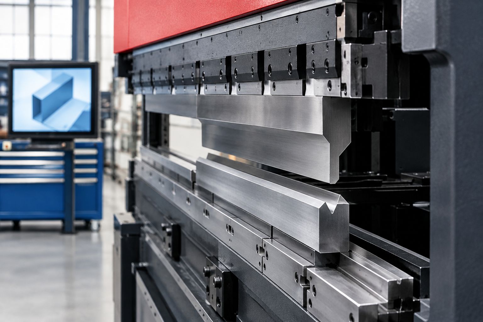
Keep inspection outside the hazardous area unless the machine's approved isolation procedure has made access safe. Do not place a hand between the punch, workpiece and die to verify alignment.
First-off verification and release
- Prepare representative material. Use a test piece representative of the specified material grade, thickness and bend length. A short coupon does not validate the loading or handling conditions of a substantially different production part.
- Run the approved trial. Follow the machine's commissioning procedure and the reviewed forming parameters. Stop if seating, retention, alignment, clearance or load behavior differs from the approved setup.
- Inspect the part. Measure bend angle, inside radius, flange dimensions and relevant drawing tolerances. Inspect surface marks, distortion and previously formed features affected by the sequence.
- Separate corrections from redesign. Make only process adjustments permitted by the approved setup. A clearance conflict, unsuitable working profile or unresolved load limit requires renewed engineering review—not a deeper stroke.
- Record the release. Save the approved tooling identifiers, segment arrangement, controller definitions, material reference and inspection result. Define which changes require reapproval.
Expected result: An inspected first-off part and a traceable setup record linking the machine, tooling, material and program.
Use 2 linked records: an interface approval record and a first-off inspection record. Together they show both mounting suitability and the achieved part geometry without treating either as proof of the other.
When the part or tooling arrangement changes
Repeat the affected checks whenever a revised drawing, different material, changed bend length or new segment arrangement enters the job. An unchanged clamping interface does not preserve approval for changed geometry or loading.
Use 3 release gates for the revised setup:
- Interface gate: Recheck seating, retention and installed height whenever the tooling stack changes.
- Process gate: Recheck radius, flange support, clearance and required force whenever the part, material or forming method changes.
- Inspection gate: Verify a new first-off part against the applicable drawing before releasing the revised job.
Keep the 2026 change log tied to the actual drawing revision and tooling arrangement. Do not approve a changed sectional set under an earlier full-length setup merely because the profiles look alike.
Troubleshooting
Punch enters the clamp but will not seat correctly
Stop installation and compare the complete tang and seating geometry with the holder drawing. Debris, damage or an interface mismatch can prevent seating; do not force the punch into place or modify retention features.
Sections produce an uneven bend line
Check segment seating, working-height consistency, joint condition and alignment using the approved inspection procedure. Then review the machine's compensation settings separately; compensation must not conceal a misassembled tooling set.
Programmed clearance differs from physical clearance
Check tool height definitions, intermediate components, lower holder references and the actual segment arrangement. Correct the documented mismatch before repeating the manufacturer's permitted motion check.
A return flange contacts the punch or holder
Recheck the complete bending sequence, including approach and withdrawal. A different sequence or reviewed working profile can address the conflict; changing the punch alone does not establish clearance around the holder.
The first-off angle misses the drawing tolerance
Confirm material identification, thickness, tooling geometry and forming method before adjusting the approved process. If the part requires a different radius or the tooling lacks suitable support, return to the geometry review rather than correcting angle alone.
Customize your workflow
Build a reusable tooling review package around the finished-part drawing. Include interface drawings, installed height, material grade, thickness, bend length, radius, flange geometry, segment layout and the proposed bending sequence.
Chinacovo's custom press brake tooling review should start with that package, not an unsupported request for an AMADA-style punch. A verified machine interface and a defined finished part are separate inputs; supply both.
For your 2026 tooling library, attach approved arrangements to the exact machine and holder configuration. Treat a transferred tool set as a new setup until the receiving machine's interfaces, controller definitions and operating limits are verified.
FAQ
How do I check AMADA press brake tooling compatibility?
Compare the installed upper clamp and lower holder with the tooling drawings, then verify retention, seating, installed height, working geometry and load limits. A matching machine brand or tang dimension alone does not establish compatibility.
Can Chinacovo tooling fit an AMADA press brake?
Chinacovo manufactures press brake tooling for fabricators using AMADA systems, but each proposed assembly requires an interface review. Confirm the actual holders, intermediate components, installed height and required part geometry before installation.
Can I use an adapter to connect a different tooling interface?
Use an adapter only when the complete assembly is approved for the machine, holders and intended loading. Recheck installed height, retention, alignment and clearance because the adapter changes the tooling stack.
Do I need different controller settings after changing tools?
Verify the controller's tool definitions and setup parameters whenever the tooling assembly changes. Use the machine manual's reference conventions and exact fields rather than copying another machine's entries.
Is matching the punch radius enough to make the required bend?
No; finished bend geometry also depends on the forming method, die geometry and material behavior. Review the required inside radius together with flange support, clearance and the approved process.
What should I send for a custom tooling review?
Send the finished-part drawing, machine and holder interface drawings, material grade, thickness, bend length, required radius and flange geometry. Include the proposed bend sequence and any existing tooling drawings or load restrictions.
Does a successful short test bend approve the full production job?
No; the production setup still requires verification for its actual bend length, loading, clearance and handling conditions. Inspect a representative first-off part and document the approved assembly before release.
One last thing
The least visible component can determine compatibility: an intermediate clamp or lower holder changes the relationship between the machine and the working profile. Before requesting a replacement tool, document those components alongside the punch and die. A tool drawing without the installed assembly leaves the connection unresolved.
Related guides
- Segmented press brake dies for box forming
- Gooseneck press brake punches
- Press brake tooling for electrical enclosures
Open this COVO engineering guide · Browse press brake tooling · Request technical support