COVO KNOWLEDGE
How to connect COVO tooling to a Trumpf press brake
Published:
Updated:
TRUMPF press brake tooling compatibility requires verified interfaces, installed height and load limits. Follow the setup checks before mounting and first bending.
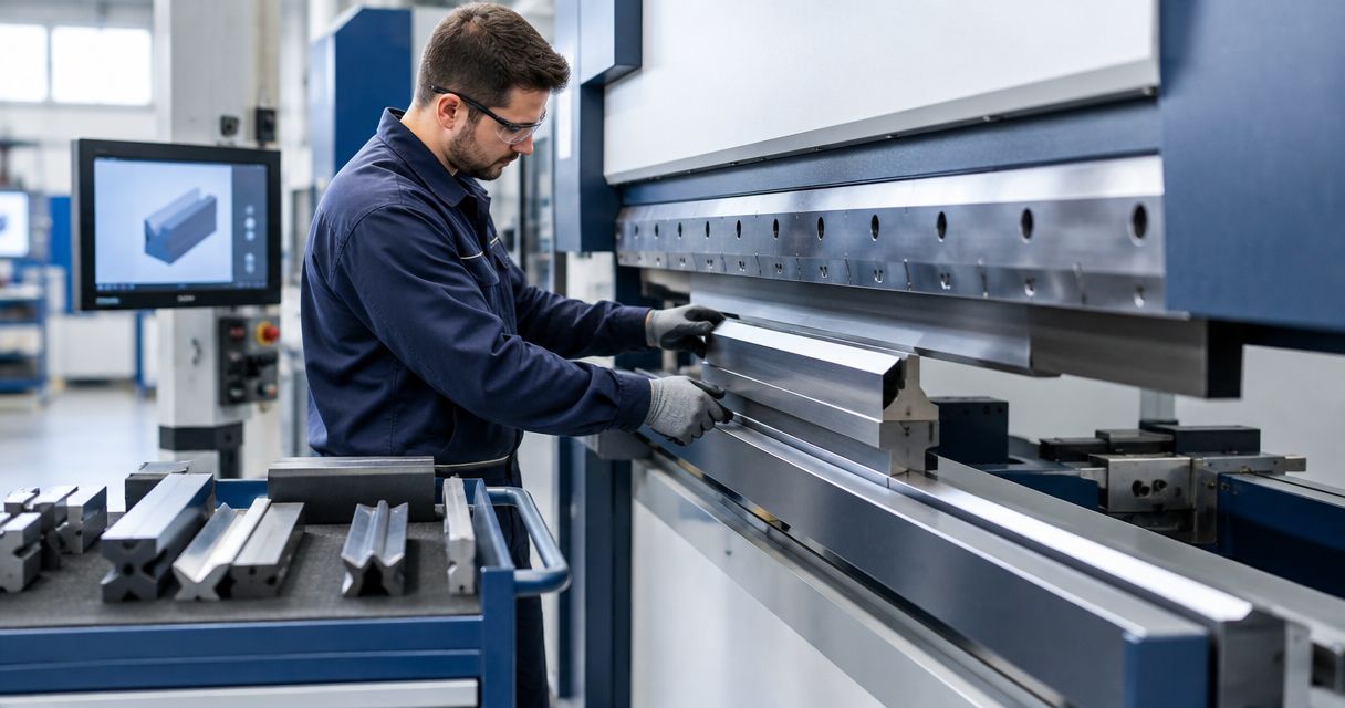
Instead of checking tool fit by trial installation, establish TRUMPF press brake tooling compatibility from the upper and lower clamping interfaces, installed height, load limits and finished-part drawing before mounting Chinacovo tooling. Then qualify the approved assembly with a controlled setup and first-part inspection under your machine’s operating instructions.
- TRUMPF press brake tooling compatibility requires matched clamping interfaces, retention, installed height and load limits—not matching brand labels.
- Chinacovo manufactures standard and custom press brake tooling for fabricators using TRUMPF systems.
- Verify punch, die and holder drawings before installation; a matching working profile does not establish interface compatibility.
- Release the setup only after confirming bend radius, flange geometry, clearance and first-part dimensions.
Why this matters
Mechanical fit is necessary, but it does not establish a usable bending setup. A punch can engage a holder while its installed height, working profile or load rating remains unsuitable for the intended part. The lower die and its support require a separate check.
For your 2026 setup records, treat compatibility as an assembly-level decision: machine, upper holder, punch, lower holder, die and workpiece. Do not approve individual components without reviewing how they work together.
Chinacovo press brake tooling is best for fabricators seeking standard or custom tools reviewed against their machine interface and finished-part geometry. Its manufacturing scope includes punches, dies, forming tools and accessories; that scope does not establish compatibility with every installed holder configuration.
Before you start
- Machine access and documentation: Obtain the exact machine model, installed upper and lower holder identification, applicable operating instructions and tool-loading procedure. Have a trained operator responsible for mounting, setup and machine operation.
- Part and tooling specifications: Assemble the finished-part drawing, material grade, thickness, bend length, required radius, flange geometry and tolerances. Include dimensioned punch, die and holder drawings, with permissible loads and their stated units.
- The overlooked gotcha: Identify any replacement clamps, intermediate holders or adapters already installed. The machine nameplate alone does not describe the current clamping interface, and an added component changes the installed-height calculation and assembly load review.
Do not start installation with unresolved interface dimensions or load limits. Photographs help identify a configuration, but they do not replace dimensioned drawings for mating surfaces and retention features.
Machine and interface record
- Identify the machine and its actual holder configuration. Record the model and the identifiers on the upper holder, lower holder and any intermediate components. Keep the machine’s original specification separate from the equipment currently installed.
- Document 2 interfaces: upper and lower. For the upper interface, capture the punch tang, seating surfaces, retention features and insertion method. For the lower interface, capture the die base, locating surfaces, holder engagement and support arrangement.
- Match the proposed tool drawings to the installed holder drawings. Check dimensions from the same datums, not from whichever surface is easiest to measure. Include tolerances where they determine seating or retention.
- Record the prescribed loading and unloading method. Confirm whether the installed arrangement requires lateral insertion, vertical loading or another manufacturer-defined procedure. Do not infer the method from the tool’s appearance.
- Create 1 setup record per approved assembly. Identify the exact punch, die, holders and intermediate components, rather than storing an approval against the machine brand alone.
Expected result: You have a traceable interface record showing how each tool seats, locates and remains retained. Any mismatch becomes a drawing-review issue before a tool approaches the machine.
Choose the assembly route
The following routes address different engineering conditions. None bypasses the holder, height or load checks.
| Assembly route | Best for | Advantage | Constraint to verify |
|---|---|---|---|
| Direct interface match | A tool whose mounting geometry matches the installed holder | Avoids adding an intermediate component | Retention, seating, installed height and load limits still require confirmation |
| Approved adapter assembly | A documented interface conversion | Connects otherwise different mounting interfaces | Adds an interface and changes the assembly height; obtain ratings and approval for the complete stack |
| Custom tool design | Part geometry or mounting requirements that standard tools do not satisfy | Allows the mounting and working geometry to be reviewed together | Requires complete machine-interface and finished-part specifications before design approval |
An adapter is not a general repair for a nearly matching tang. Likewise, a custom working profile does not correct an incorrectly specified mounting interface.
Tool-stack and geometry review
- Establish the installed height of the complete assembly from the applicable machine and tooling datums. Include intermediate holders and adapters. Do not substitute overall loose-tool dimensions for the machine’s tool-height definition.
- Check the assembly against the machine’s permitted setup envelope. Verify opening, stroke requirements and working position using the machine documentation. Include the space required to insert, support and remove the workpiece.
- Review the punch profile against the finished-part drawing. Check nose radius, included angle, relief geometry and clearance to previously formed flanges. A profile that forms the first bend can still obstruct a later bend.
- Review the die opening, shoulder geometry and support against the material and bending method. Confirm that the flange has the required support and that the specified geometry is achievable without assuming the punch nose alone determines the finished radius.
- Check bend length and segment arrangement. Confirm the working length, segment seating, joint locations and end clearances. Keep segment interfaces out of features where they would compromise the required surface or geometry.
- Evaluate the complete bend sequence. Check workpiece clearance to the punch body, holders, machine structure and backgauge components at each operation—not only at the final position.
Expected result: The tool stack fits the machine envelope, and the proposed profiles accommodate the required radius, flange geometry and bend sequence. Record unresolved conflicts before approving the assembly.
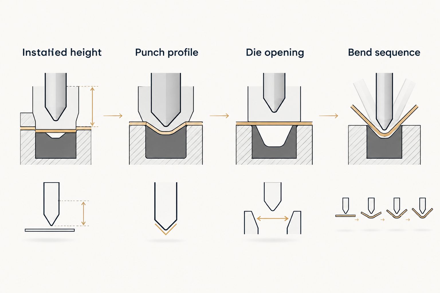
For a 2026 drawing package, identify the revision of every component used in the stack. A revised punch profile or holder arrangement requires another clearance check even when the finished-part drawing is unchanged.
Load and setup approval
- Calculate the bending requirement using a validated method appropriate to the material grade, thickness, bend length, die opening and forming process. Keep material assumptions visible in the setup record.
- Compare the required load with the machine and every load-bearing tooling component. Include punches, dies, holders and adapters. The lowest applicable limit governs the assembly, subject to each manufacturer’s stated loading conditions.
- Distinguish total force from load per unit length. Record whether a rating is stated in kN, kN/m or another unit, and convert consistently. Never compare a total-force calculation directly with a linear-load rating.
- Check the actual loaded length and load distribution. A short bend, interrupted contact or off-center operation requires review under the applicable tool and machine instructions; unused tool length does not automatically increase the permissible load.
- Confirm the forming method. Air bending, bottoming and hemming do not share an interchangeable load calculation. Do not reuse an air-bending approval for a closing or special-forming operation.
- Release the setup package only after resolving load, geometry and interface checks. Include the component identifiers, drawings, material specification, bend sequence and inspection requirements.
Expected result: The proposed operation falls within documented machine and tooling limits, and the operator has an approved setup package rather than an unsupported estimate.
Use the applicable documentation when entering tool geometry and setup data into the controller. Field names and tool-library structures depend on the installed control; do not substitute a generic menu sequence for the machine’s instructions.
Installation and first-part verification
- Follow the machine’s prescribed safe setup procedure before handling tooling. Apply required isolation and tool-support measures. Keep personnel clear of pinch points and never use powered machine motion to force a tool into its holder.
- Inspect mating surfaces before mounting. Remove contamination using the approved cleaning method, and inspect seating surfaces and retention features for damage. Stop if burrs, cracks or deformation prevent proper engagement.
- Install the upper and lower tools using the documented loading method. Confirm complete seating, engagement and retention before moving to the next setup operation. Never modify the tang, clamp or retention feature to obtain a trial fit.
- Enter the approved tool and process data. Verify the dimensional references, forming method and applicable load settings against the setup package. A previously saved program is not evidence that the new tool assembly matches it.
- Perform the prescribed setup verification and controlled first bend. Use the machine’s approved setup functions, guarding and operator procedure. Do not override protective functions to obtain clearance or observe tool movement.
- Inspect the first part against the drawing. Measure bend angle, radius, flange dimensions and relevant feature positions. Check surface condition and interference through the remaining bend sequence before production release.
Expected result: The tools remain correctly seated and retained, and the first part satisfies the specified geometry. A successful clamp check alone does not release the job.
A 2026 first-part record should identify both the tooling assembly and the material used. Separate verification into 3 stages: mounting, forming and inspection so a dimensional correction does not conceal an unresolved mounting problem.
Requalification after a tool or part change
Use a shorter requalification workflow when a previously approved job changes, but retain every check affected by the change. Reusing a program does not transfer approval to a different assembly.
- Identify the change: material grade, thickness, bend length, punch profile, die opening, segment arrangement, holder or adapter.
- Reopen the affected checks. A holder change requires interface and installed-height review; a material change requires load and forming review; a flange change requires sequence and clearance review.
- Update the tool record and controller data where applicable. Preserve the earlier approved revision rather than overwriting the evidence of its configuration.
- Complete a controlled first-part inspection before releasing the revised job.
Best for: Repeat jobs with a documented baseline and a clearly identified change. The benefit is focused review; the limitation is that an incomplete change record leaves affected checks unidentified.
Keep the baseline and revised approval together in your 2026 records. If you cannot identify the previous assembly, use the full qualification workflow instead.
Troubleshooting
The punch enters the holder but will not seat
Check tang dimensions, seating datums, retention geometry and contamination against the drawings. Do not grind the tang or force the clamp closed. Return the mismatch for engineering review.
The assembly clamps, but the part hits the tool body
Review punch relief, installed height, flange geometry and the operation sequence. Check the complete workpiece position at the affected bend. Changing the sequence requires another review of the remaining operations.
The setup exceeds a tooling load limit
Recheck units, loaded length, material assumptions, die opening and forming method. Do not increase the load setting to bypass the limit. Revise the process or specify an assembly rated for the required operation.
Bend angle or flange dimensions differ from the drawing
Confirm material, tool geometry, program data, backgauge references and measurement method before adjusting the process. Inspect seating as well. Do not compensate for an incorrectly mounted tool through program changes.
Results differ after changing tool segments
Check segment seating, alignment, working height and joint arrangement. Confirm that the installed segments match the approved setup record. Reinspect the first part after correcting the assembly.
Customize your workflow
For a Chinacovo tooling review, send the finished-part drawing alongside the machine-interface package—not as a separate request without mounting information. Include material grade, thickness, bend length, radius, flange geometry, bend sequence, surface requirements and applicable load constraints.
Use the custom press brake tooling guide for OEM fabricators to extend the review from replacement tooling to part-specific profiles. Custom engineering must address the mounting interface and forming geometry together.
Standard tooling simplifies specification when its interface and profile satisfy the job. Custom tooling addresses requirements that standard geometry does not satisfy, but it requires a more complete drawing package. Choose from verified requirements, not from a profile photograph.
FAQ
Will Chinacovo tooling fit any TRUMPF press brake?
Compatibility must be verified against the installed upper and lower holders, not the machine brand alone. Review the clamping interfaces, retention, installed height and load limits before mounting.
What drawings do I need to check TRUMPF press brake tooling compatibility?
You need dimensioned drawings of the installed holders, proposed punches and dies, plus the finished-part drawing. Include intermediate components, material grade, thickness, bend length and required geometry.
Can I use an adapter to connect a different tooling interface?
Use an adapter only when the complete assembly has documented interface compatibility and applicable ratings. The adapter adds an interface and changes the installed-height and load review.
Does a matching punch tang prove the tooling is compatible?
No, a matching tang does not establish complete compatibility. Seating, retention, lower-tool fit, installed height, clearance and permissible load also require verification.
Can I reuse the existing bending program after changing tools?
Reuse the program only after checking its tool and process data against the revised assembly. Requalify affected interface, geometry and load checks, then inspect the first part.
How do I compare tool load ratings with required bending force?
Compare ratings and calculated requirements using consistent units and the manufacturer's stated loading conditions. Total force and load per unit length are different quantities; review the actual loaded length and distribution.
When should I request custom press brake tooling?
Request custom tooling review when verified standard interfaces or working profiles do not satisfy the machine and finished-part requirements. Provide both the mounting drawings and the required forming geometry before design review.
One last thing
The setup record should identify the holders, not just the punch and die. Replacing a holder changes the mounting assembly even when the working tools remain unchanged. Make holder identification a required field in your 2026 approval record.
Related guides
- TRUMPF-compatible press brake tooling suppliers
- Segmented press brake dies for box forming
- Press brake dies ranked by tonnage capacity
Open this COVO engineering guide · Browse press brake tooling · Request technical support