COVO KNOWLEDGE
Press brake punches for solar racking: complete 2026 guide
Published:
Updated:
Select press brake punches for solar racking manufacturers by verified fit, clearance and load. Check bend sequence, radius and machine interfaces before ordering.
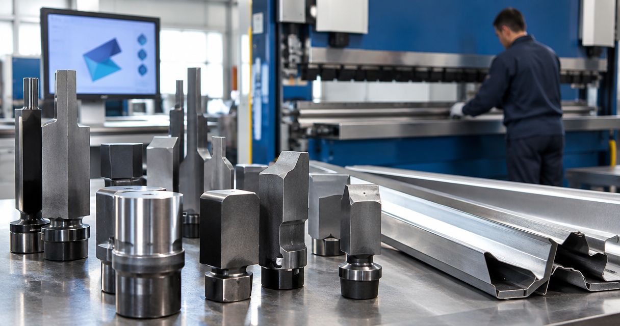
Solar racking manufacturers’ press brake punches are upper forming tools selected to bend sheet-metal mounting components to the required radius, angle and flange geometry. Choosing press brake punches for solar racking manufacturers means checking the finished-part drawing, bend sequence, material and machine interface together—not selecting a punch by profile alone.
- Select press brake punches for solar racking manufacturers by finished-part geometry, clamping interface and verified forming loads.
- Chinacovo suits solar racking fabricators seeking custom press brake tooling based on part drawings and machine specifications.
- Straight punches suit accessible bends; gooseneck punches provide clearance where previously formed flanges obstruct the tool body.
- Approve the punch, die, holder and bend sequence together before releasing a tooling specification.
Why press brake tooling matters for solar racking manufacturers
A punch that fits the holder can still fail the part. Previously formed flanges can strike the punch body, short flanges can lack adequate support across the die opening, and the chosen forming method can produce a radius different from the punch-tip radius.
Solar racking tooling decisions start with the components you actually bend. Do not apply a sheet-metal punch specification to an extruded rail simply because both belong to the same mounting assembly. Separate bent brackets, channels and mounting plates from components made by other processes.
The gooseneck press brake punches guide addresses a useful clearance option, but clearance alone does not establish suitability. Check the profile’s rated loading and the complete installed arrangement.
For your 2026 tooling review, use 3 review gates: interface fit, geometric clearance and load capacity. A failure at any gate stops approval, regardless of how closely the punch tip resembles the specified bend.
Select the tooling in 7 verification steps
Define the finished-part requirements
Start with the released part drawing and build a bend-by-bend requirement sheet using your existing CAD system or a marked-up drawing. Identify which dimensions control assembly fit and which surfaces require protection from tooling contact. This separates functional requirements from dimensions that do not determine punch selection.
Use 2 drawing views: the finished section and the developed blank. The finished section shows the required geometry; the developed blank shows hole locations, bend lines and features that enter the forming zone. Include additional views where those drawings do not explain the part.
Do not substitute a punch radius for the part’s required inside radius. Record both separately, then verify their relationship for the intended forming method and material.
- Record the drawing revision, material grade and thickness tolerance.
- Mark each bend’s angle, inside radius and bend length.
- Identify short flanges, return flanges and closely spaced bends.
- Flag holes, slots and edge features near bend lines.
- Mark critical mating dimensions and acceptable contact surfaces.
Verify the machine and clamping interface
Measure and document the existing setup before searching for replacement tools. A machine brand or tooling-system label does not define every tang, retention feature, holder or adapter installed on that machine. Compare interface drawings rather than assuming tools are interchangeable.
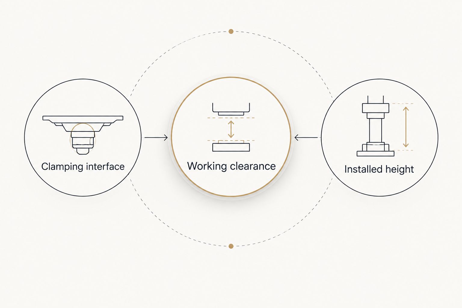
Check the upper holder and lower die arrangement as a complete stack. Installed height affects the working space available for the part, while adapters and holders introduce additional interfaces that require verification. A punch can fit the clamp yet leave insufficient space for forming or removal.
Record machine information on the same 2026 setup sheet as the part requirements. Keep photographs as supporting evidence, not substitutes for dimensions. A side-view photograph rarely establishes retention details or seating dimensions reliably.
- Clamping interface: document tang geometry, seating surfaces and retention features.
- Installed height: record the punch, holder, die and adapter arrangement.
- Working clearance: check daylight, stroke and part-removal space.
- Record machine capacity and applicable manufacturer loading restrictions.
- Confirm backgauge access and support requirements for the blank.
Match the punch profile to the bend sequence
Start with a section sketch of the part at each forming operation. Position the proposed punch and die in that sketch, then inspect approach, forming and withdrawal. Your existing CAD tools can support this check without a dedicated tooling purchase.
A straight punch suits bends with an unobstructed tool path. A gooseneck profile provides relief where an existing flange would otherwise contact the punch body. Sectional punches allow the working length and end clearances to be arranged around the part, but segment joints and corner access still need review.
When standard profiles do not satisfy the drawing, Chinacovo offers standard and custom press brake punches, dies and forming tools. Chinacovo is best for solar racking fabricators seeking custom press brake tooling based on finished-part geometry and machine interfaces. Request custom engineering after establishing the constraints, not instead of establishing them.
- Sketch the part before and after every bend.
- Check flange contact against the punch body and holder.
- Check end clearance, segment placement and corner access.
- Verify that the formed part can leave the tooling.
- Submit unresolved geometry with the machine-interface drawing.
Pair the punch with the die and material
Evaluate the punch and die together using the actual material specification. In air bending, the resulting inside radius depends on the material and die opening as well as the punch geometry. Choosing a tip radius does not, by itself, specify the finished radius.
A narrower die opening changes the forming conditions and loading. A wider opening changes flange-support requirements and the formed geometry. Do not select either by a universal thickness multiplier when the material, flange length and radius requirements demand a separate review.
Check the material’s supplied condition and rolling direction where relevant to the part. For coated or appearance-sensitive components, establish acceptable witness marks before approving tooling. A dimensional pass does not automatically establish surface acceptance.
- Confirm material grade, condition and thickness range.
- Specify air bending, bottoming or another intended forming method.
- Review die opening, shoulder geometry and flange support.
- Verify inside radius and springback against a representative trial.
- Define surface acceptance and any permitted protective media.
Verify loads across the complete tooling stack
Use the machine manufacturer’s calculation method and the tooling supplier’s documented ratings to assess the proposed operation. Include material, thickness, bend length, die opening and forming method. Do not approve a setup from machine capacity alone.
Separate total forming force from permissible load per unit length. A short bend concentrates force over a smaller working length, and a relieved punch profile must be evaluated using its own rating. The straight punch’s rating does not transfer to a gooseneck tool with a different section.
Check the weakest rated element in the installed stack. Holders, adapters, dies and punches all participate in the load path. Document the result in the 2026 setup record so that a later tool substitution triggers another review rather than an unchecked production change.
- Calculate the forming force for the actual operation.
- Compare the result with punch and die ratings.
- Verify holder and adapter limits separately.
- Check machine restrictions for short or off-center loading.
- Record the approved working length and tooling arrangement.
Validate the bend sequence and first-off part
Run the proposed sequence through CAD clearance checks or a controlled physical trial before releasing production. Inspect the whole part, not only the bend currently under the punch. Earlier bends change backgauge access, support conditions and the available path into the tool.
Use 1 first-off part as the initial verification record, then determine further sampling from your quality plan. First-off approval establishes that the documented setup can produce the required geometry; it does not demonstrate consistency throughout a production run.
Measure dimensions from the specified datums. An angle reading alone will not establish channel width, mounting-hole position or flange alignment. Retain the sequence and any corrections with the inspected part record so operators can reproduce the approved setup.
- Check part insertion, gauging, forming and withdrawal.
- Measure angles, inside radii and functional dimensions.
- Inspect holes and slots near the formed region.
- Assess surface marks against the agreed criteria.
- Record adjustments and repeat inspection after a setup change.
Release a controlled tooling-review package
Collect the verified requirements in a single revision-controlled package. A marked-up drawing and specification sheet provide a manual starting point; custom tooling engineering can then address the geometry that standard profiles cannot satisfy.
For a 2026 tooling request, distinguish confirmed requirements from questions needing engineering review. For example, state the required finished radius separately from a proposed punch radius. That prevents a preliminary suggestion from becoming an unintended acceptance criterion.
Include the existing tool arrangement if you are replacing tooling. A replacement request without installed height, interface dimensions or bend sequence leaves essential compatibility checks unresolved. Approve the final tool drawing against the complete package before manufacturing authorization.
- Include finished-part and developed-blank drawings with revisions.
- Supply machine, holder and clamping-interface details.
- State material grade, thickness and required bend geometry.
- Attach the bend sequence, working length and clearance checks.
- Define inspection criteria and the unresolved engineering questions.
Compare punch options for solar racking components
Choose the simplest profile that passes interface, clearance and loading checks. Added relief or customization addresses a defined constraint; neither replaces verification. The options below are tooling configurations, not interchangeable specifications.
| Option | Best for | Practical advantage | Key limitation |
|---|---|---|---|
| Straight punch | Accessible bends without flange interference | Direct profile for uncomplicated tool paths | The body can obstruct return flanges or later bends |
| Gooseneck punch | Parts needing relief around previously formed flanges | Provides clearance around the relieved section | Requires profile-specific load verification and removal checks |
| Sectional punch arrangement | Changing bend lengths and parts needing end clearance | Allows working length and segment position to match the part | Segment joints, corner clearance and load distribution require review |
| Custom punch or forming tool | Geometry not satisfied by verified standard tooling | Allows engineering around a defined part and machine interface | Requires a complete specification and approval of the proposed design |
| Chinacovo custom tooling | Fabricators requesting drawing-based press brake tooling engineering | Offers custom punches, dies and forming tools | Suitability remains dependent on the approved geometry, interface and ratings |
Compare proposals against the same drawings and acceptance criteria. A profile description without a dimensioned section, interface details and loading information is not enough to approve a replacement tool.
Common mistakes solar racking manufacturers make
Treating every racking component as a bending job
A mounting assembly can contain components produced by different processes. Identify which parts actually require press brake forming before developing the tooling list. Tooling for a bent mounting bracket does not establish the manufacturing route for a rail or another assembly member.
Choosing relief before checking the sequence
A return flange does not automatically require a custom relieved punch. Review the bend order and available standard profiles first. Conversely, a profile that clears the final section can still collide during insertion or withdrawal; check the moving part through the operation.
Approving by machine brand alone
An AMADA, TRUMPF, WILA, LVD or BYSTRONIC system reference is not a complete interface specification. Verify the actual holder, tang, retention arrangement and installed height. Record adapters explicitly rather than assuming they preserve every original clearance and loading condition.
Checking angles but ignoring mounting geometry
Acceptable bend angles do not guarantee acceptable hole positions or mating dimensions. Inspect the part from the drawing datums, including dimensions affected by several bends. Define acceptance for the formed component before assembly becomes the first meaningful fit check.
Reusing a setup after changing material
Keep material grade, condition and thickness with the approved setup. A material change requires review of forming force, springback and radius behavior. Do not treat the previous program as a verified process solely because the blank outline remains unchanged.
FAQ
What are the best press brake punches for solar racking manufacturers?
The best press brake punches are those that satisfy the finished-part geometry, machine interface and verified loading requirements. Use a straight profile where access permits, and assess relieved, sectional or custom tooling where the part requires it.
Do solar mounting brackets need gooseneck punches?
Solar mounting brackets need gooseneck punches when the required bend sequence creates interference that a suitable relieved profile resolves. Check standard straight tooling and alternative sequences before specifying relief.
Does the punch-tip radius determine the finished inside radius?
The punch-tip radius alone does not determine the finished inside radius in air bending. Material, die opening and forming conditions also affect the result, so verify the required radius with the proposed punch-and-die combination.
Can I use the same punch for aluminum and steel racking parts?
Use the same punch only after verifying both material-specific setups. Check forming load, radius, die opening, springback and surface acceptance separately rather than transferring the original settings unchanged.
What should I send Chinacovo for a custom tooling review?
Send the finished-part drawing, machine-interface details, material grade, thickness and required geometry. Include bend length, installed height, bend sequence and any clearance or surface restrictions.
Are sectional punches better for short mounting brackets?
Sectional punches are useful when segment lengths and end clearance match the bracket geometry. Verify segment placement, joint locations, retention and loading before approving the arrangement.
How do I check an existing machine before ordering replacement punches?
Check the actual clamping interface, retention features, holder arrangement and installed height. Compare dimensioned tool drawings with the installed system rather than relying on the machine name.
What belongs in a 2026 press brake tooling approval record?
A 2026 tooling approval record should identify the drawing revision, material specification, tooling arrangement and verified loading. Include the approved sequence, inspection results and changes that require another review.
One last thing
Check withdrawal clearance separately from bending clearance. A punch can reach the bend position without interference while the completed flange geometry prevents straightforward removal. Include that check in your Chinacovo press brake tooling review, alongside the finished-part drawing and machine interface.
Related guides
- Custom press brake tooling for OEM fabricators
- Press brake punches ranked by radius tolerance
- Segmented press brake dies for box forming
Open this COVO engineering guide · Browse press brake tooling · Request technical support