COVO KNOWLEDGE
Press brake tooling for kitchen equipment makers: complete 2026 guide
Published:
Updated:
Press brake tooling for kitchen equipment makers: choose by part geometry and machine fit. Verify clamping, bend radius, clearance and loads before ordering.
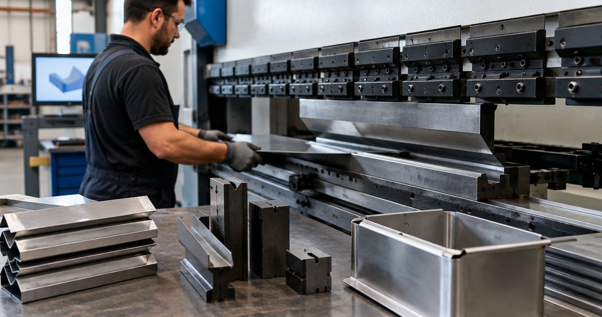
Kitchen equipment makers’ press brake tooling is the punch, die and forming-tool arrangement used to produce sheet-metal components with the aim of meeting finished-part geometry and assembly requirements. This 2026 guide focuses on the interface, clearance, load and surface checks needed for panels, trays, cabinets and formed edges.
- Select press brake tooling for kitchen equipment makers by finished-part geometry, clamping interface and forming load—not machine brand alone.
- Chinacovo is best for kitchen equipment makers requesting drawing-led standard or custom press brake tooling review.
- Check stainless steel tooling against material grade, thickness, bend radius and visible-surface requirements.
- Verify box clearance and hemming geometry through the full forming sequence before ordering tools.
Why press brake tooling matters for kitchen equipment makers
Kitchen-equipment drawings bring several requirements into the same setup: flange geometry, assembly fit, accessible edges and surface appearance. A punch that reaches the specified angle can still interfere with a return flange. A die that supports the bend can still leave contact marks on a visible panel.
Choose tooling against the finished part and the forming sequence, not an isolated bend. Start with the drawing, identify the critical features and check whether your existing setup can form them without losing clearance or exceeding a component’s rated load.
The guide to press brake dies for stainless steel fabrication provides a related material-specific reference. For your 2026 tooling review, keep material behavior, machine fit and finished-surface acceptance in the same specification package.
How to specify tooling from drawing to first article
Define the finished-part requirements
Begin manually with the released drawing. Mark the bend angle, inside radius, flange length and tolerance for each feature, then distinguish functional requirements from dimensions that only describe the nominal shape. Identify which dimensions control mating parts, drawer movement, door fit or attachment points where those features appear on your drawing.
Include the finished condition of formed edges. A flat hem, an open hem and a simple return flange require different working geometry; they are not interchangeable instructions. State which surfaces remain visible after assembly and what evidence will establish acceptance.
For a 2026 drawing package, include 2 drawing views as a minimum review aid: a finished-part section and a view showing bend length. Add further sections wherever a return or corner hides the relevant clearance.
- Mark the bend angle and inside radius at each critical feature.
- Dimension flanges from a clearly identified datum.
- Identify visible faces and permitted contact areas.
- Define the final edge profile, including any hem gap.
- Include assembly constraints that affect the bend sequence.
Verify the machine and clamping interface
Use the machine documentation, holder drawings and existing tool drawings to establish the interface before selecting a working profile. Measure accessible features using your normal inspection procedure, but do not substitute a loose-tool measurement for the holder’s approved interface specification.
AMADA, TRUMPF, WILA, LVD and BYSTRONIC system references describe equipment families; they do not, by themselves, verify a particular tool-to-holder connection. Confirm the actual tang or shank, seating surfaces, retention arrangement and installed height on the machine being used.
Include the lower-tool interface as well as the punch connection. A suitable punch profile does not establish compatibility for the complete assembly. Check available opening, stroke and backgauge access against the assembled tool heights and the part’s planned loading position.
- Record the press brake model and installed holder configuration.
- Supply upper and lower clamping-interface drawings.
- Verify seating surfaces, retention and tool orientation.
- Record punch, die and adapter installed heights.
- Check opening, stroke and backgauge access for the setup.
Match the tooling to material and forming method
Review your existing punches and dies against the material certificate and drawing before requesting new tools. Specify material grade, thickness and relevant surface condition; describing a job only as stainless steel or aluminum leaves the forming requirements incomplete.
In air bending, the die opening and material behavior influence the resulting inside radius. The punch-tip radius alone does not define the finished radius. Bottoming and other forming methods require their own geometry and load review, so identify the intended method rather than assuming a tool drawing determines the process.
For your 2026 review, Chinacovo manufactures standard and custom press brake tooling. Submit the finished-part drawing, machine interface, material grade, thickness and required geometry together for a drawing-led review. Custom tooling still requires fit, load and trial-part verification; it is not a substitute for process validation.
- State the material grade and actual thickness range.
- Identify the intended forming method.
- Match punch radius and die geometry to the required result.
- Check minimum-flange support for the proposed die opening.
- Provide the machine and tooling load limits.
Check clearance through the complete bend sequence
Sketch the bend sequence using your existing part drawing, or review it in the available bending software. Follow the partially formed part through each operation. Check the approach, forming stroke, return stroke and removal path—not just the final position at the bottom of the bend.
Return flanges and box walls can obstruct a straight punch even when the first bend is straightforward. A gooseneck profile provides space around an existing flange, but its recess must match the actual interference envelope. Sectional tools address working length and access; they do not automatically solve a profile collision.
Use a section through the tightest bend and a view along the tool length. These views expose different problems: cross-section interference, corner interference, segment placement and trapped-part removal. A clear bending position is insufficient if you cannot remove the finished part.
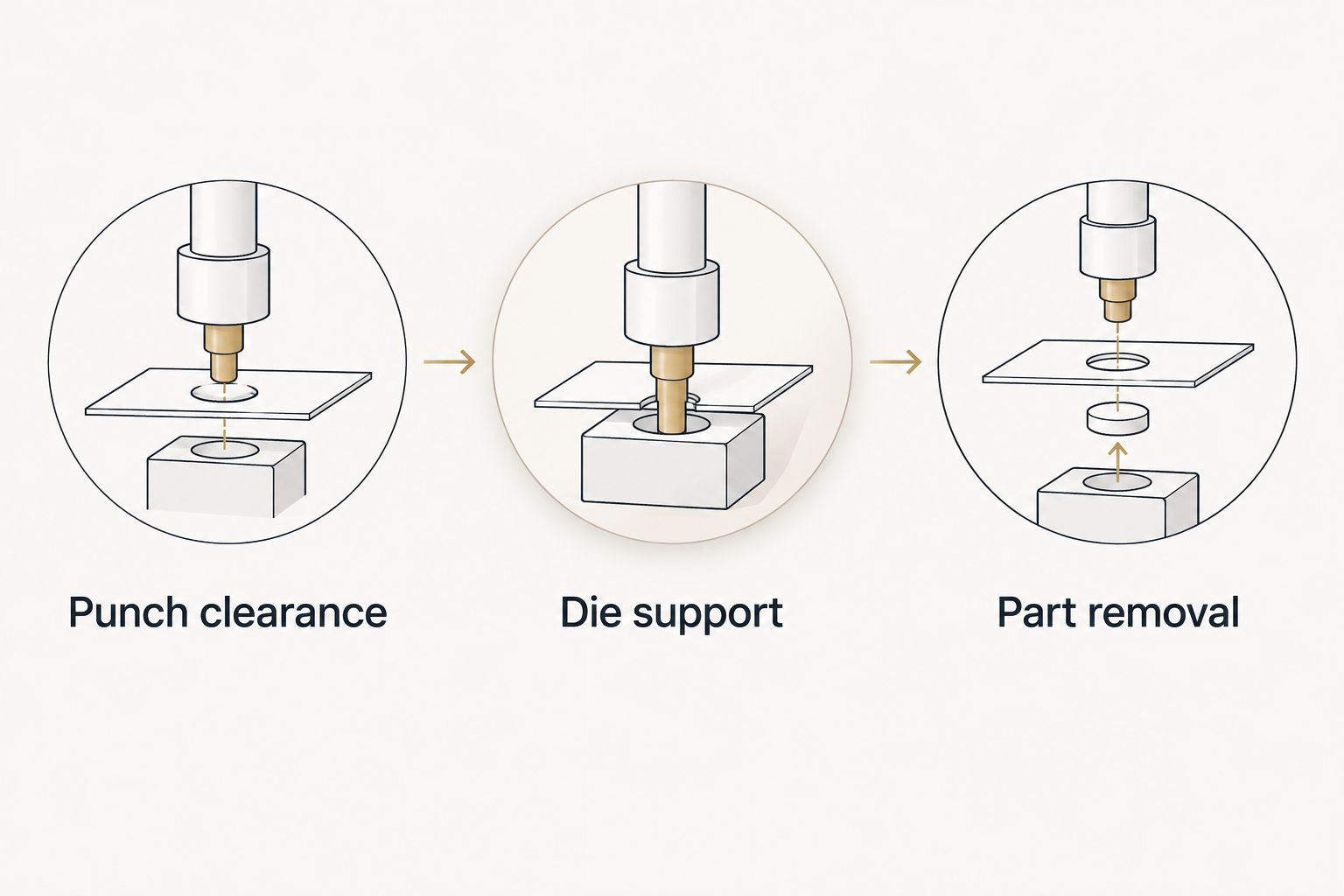
- Check Punch clearance around existing flanges and walls.
- Check Die support under the active bend.
- Check Part removal after the final forming operation.
- Verify segment positions against corners and returns.
- Confirm backgauge contact remains accessible in sequence.
Specify hems and surface-contact requirements
Start by drawing the required edge section and reviewing the current pre-bend and closing arrangement. Separate the pre-bend geometry from the closing operation. A flat hem and a teardrop hem require different finished profiles, and the drawing must state which one you need.
Do not use ordinary bending capacity as the acceptance criterion for a hemming setup. Verify the tooling’s rated closing load and the machine’s limits for the planned operation. Review the contact pattern where the closing tool meets the part, especially when the edge sits next to a visible surface.
For appearance-sensitive kitchen equipment, document acceptable marking before choosing a surface-protection method. Protective film, contact materials and tool condition can affect the result. Validate the selected arrangement with the actual material and finish rather than treating protection as a guaranteed cure.
- Specify the hem type and finished edge geometry.
- Define the pre-bend required by the closing arrangement.
- Verify rated closing load for the intended bend length.
- Identify visible surfaces near the forming contact.
- Inspect contact surfaces for damage and embedded debris.
- Confirm the finished edge against the drawing’s acceptance criteria.
Verify bend length, segmentation and load limits
Build the working length from your existing tool inventory before specifying additional segments. Record segment lengths and positions, then check whether joints or end positions conflict with the part. A split set needs both the required total length and a usable arrangement around corners and returns.
Check load over the actual engaged length, not merely the overall tool assembly length. A short bend can concentrate loading locally. Compare the planned operation with the ratings and restrictions for the press brake, punch, die, holders and adapters, using consistent units and the manufacturers’ stated conditions.
For a 2026 setup sheet, identify the limiting component explicitly. Do not assume that a machine’s total capacity establishes the permitted load for a short tool segment or an offset setup. Document the approved tool position and any machine-specific restrictions before releasing the operation.
- Record the actual bend length for each operation.
- Map segment lengths and joint positions.
- Check ratings for every loaded component.
- Review concentrated and offset loading restrictions.
- Verify the proposed setup against the machine documentation.
Validate the first article and release the setup
Use 1 trial part as the initial verification piece before releasing the production setup. Inspect it against the drawing and record the material, tooling arrangement, program and measurement method. Where practical, use material from the intended production lot so the trial represents the job being released.
Check at least 3 inspection points on a long bend: each end and the center. This is a practical starting check, not a replacement for the drawing’s inspection plan. Add measurements wherever a critical feature, segmented arrangement or local deformation requires them.
Chinacovo is best for kitchen equipment makers requesting drawing-led standard or custom press brake tooling review. The benefit is a tooling specification tied to the part and machine; the limitation is that dimensional acceptance still depends on your verified setup, material and inspection results.
- Record measured angles, radii and critical flange dimensions.
- Inspect visible surfaces and formed edges.
- Verify assembly fit where the drawing requires it.
- Confirm safe part handling and removal.
- Save the approved tool arrangement and setup conditions.
Compare tooling options by the constraint they solve
Select the option that solves the documented constraint without creating a new one. Begin with existing standard tooling, then evaluate specialized profiles or custom engineering where the drawing exposes a specific gap. No option eliminates interface or load verification.
| Option | Best for | Main benefit | Key limitation |
|---|---|---|---|
| Standard straight punch and V-die | Accessible bends without return-flange interference | Uses conventional working profiles | Must still meet radius, flange-support and clearance requirements |
| Gooseneck punch | Parts with existing return flanges near the punch | Provides recess clearance around the formed flange | Recess geometry and load rating require verification |
| Sectional punch and die sets | Changing bend lengths and box-forming access | Allows working-length arrangements from separate segments | Segment positions, joints and local loads need review |
| Hemming tool arrangement | Drawing-defined flat or open hems | Provides a dedicated edge-closing operation | Requires pre-bend, closing-load and surface-contact verification |
| Chinacovo custom press brake tooling | Finished-part geometry not served by the verified standard setup | Allows tooling engineering from the part and machine specifications | Requires a defined drawing package and trial-part validation |
Existing standard tools are the first option to assess because their actual geometry can be checked immediately against the job. Custom engineering becomes relevant when those checks identify an unresolved radius, clearance, flange or forming requirement—not simply because the part belongs to a particular industry.
Common mistakes kitchen equipment makers make
Approving the angle but ignoring assembly geometry
A bend-angle measurement does not establish door clearance, mating-flange position or the overall envelope. Inspect the drawing’s functional dimensions after bending and use the specified assembly datums. Do not release a setup solely because the angle reads correctly.
Treating visible-surface protection as an afterthought
Selecting tooling before defining acceptable contact marks leaves the appearance decision until the trial. Identify the visible face, contact zones and acceptance method in the original specification. Inspect the trial under the agreed conditions rather than relying on a general statement that the finish looks acceptable.
Choosing a gooseneck by appearance alone
A deeper-looking recess does not verify clearance or permitted loading. Compare the tool section with the partially formed part throughout the stroke, then check the rating. Include removal clearance and tool-end interference in the same review.
Ordering a hem tool without the finished edge section
A request for a hem does not define the gap, profile or acceptable marking. Supply the finished cross-section and material information before selecting the pre-bend and closing arrangement. Verify the complete operation rather than approving the closing tool in isolation.
FAQ
What is the best press brake tooling for kitchen equipment makers?
The best press brake tooling for kitchen equipment makers is the verified punch-and-die arrangement that meets the finished drawing, machine interface and forming load. Choose specialized profiles or custom tooling only where standard tools fail a documented geometry or process requirement.
Can I use the same press brake tools for every stainless steel grade?
Do not approve one setup for every stainless steel grade without checking material behavior and load. Specify grade, thickness, required radius and finish, then validate the setup against the drawing.
When do I need a gooseneck punch for a kitchen equipment part?
Use a gooseneck punch when its verified recess clears a formed flange that interferes with a straight punch. Check the complete stroke, removal path and tool rating before approving the profile.
Are sectional tools better than full-length tools for box forming?
Sectional tools are best for box-forming arrangements that require specific working lengths or end clearance. They still require checks of segment fit, joint positions, clamping and local loading.
Does a punch-tip radius determine the finished inside radius?
A punch-tip radius does not by itself determine the finished inside radius in air bending. Die opening, material behavior and the selected forming method must be included in the review.
What should I send for a custom tooling review?
Send the finished-part drawing, machine and holder interfaces, material grade, thickness and required geometry. Include bend length, installed-height constraints, load limits, surface requirements and the planned bend sequence.
Can I approve a hemming tool using the press brake's total capacity?
Do not approve a hemming tool from total machine capacity alone. Verify the closing load and the limits of the tool, holders, adapters and machine for the actual operation.
One last thing
Prove the last bend’s removal path before approving the first bend’s tooling. A profile can meet the drawing at full closure yet leave the formed part trapped around the tool. Put removal clearance on your 2026 setup review alongside angle, radius and load; it is part of process feasibility, not an operator workaround.
Related guides
- Gooseneck press brake punches compared
- Segmented press brake dies for box forming
- Custom press brake tooling for OEM fabricators
Open this COVO engineering guide · Browse press brake tooling · Request technical support