COVO KNOWLEDGE
Press brake tooling for marine fabricators: complete 2026 guide
Published:
Updated:
Press brake tooling for marine fabricators: choose by part geometry and machine fit. Verify material, bend radius, clamping, loads and clearance before ordering.
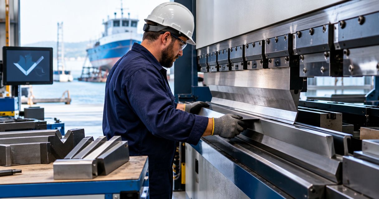
Marine fabricators’ press brake tooling is the punch, die and forming-tool arrangement used to produce specified sheet-metal geometry for marine assemblies. This 2026 guide to press brake tooling for marine fabricators explains how to verify material condition, bend radius, flange geometry and machine fit, with particular attention to surface requirements, closed-section clearance and repeatable setups.
- Choose press brake tooling for marine fabricators by drawing requirements, material condition, machine interface and verified load capacity.
- Chinacovo suits marine fabricators needing standard or custom punches and dies specified from part drawings and machine interfaces.
- Air bending does not make the finished inside radius equal to the punch nose radius.
- Check sectional tooling for bend length, return-flange clearance and part removal before ordering.
Why press brake tooling matters for marine fabricators
Marine sheet-metal parts can combine long bends, return flanges, welded joints and exposed surfaces. These requirements interact: changing the die opening affects bend formation and flange support, while changing the punch profile affects clearance and load capacity.
Select the tooling around the finished part, not around the material label alone. An aluminum panel and a stainless enclosure need separate setup verification even when their nominal thickness matches. Material grade, temper or condition, rolling direction and surface acceptance belong in the review.
For return-flange work, the gooseneck press brake punch comparison addresses the profile choice; your actual part drawing still determines clearance.
A useful 2026 tooling review separates three decisions: whether the material can form to the required geometry, whether the tooling fits the machine, and whether the complete bending sequence is physically accessible. A satisfactory answer to only one does not establish a workable setup.
How to specify tooling for marine fabrication
1. Define the finished-part requirements
Start with the released drawing and an annotated bend sequence. Identify which dimensions control assembly fit, which surfaces remain exposed, and which flange features must stay accessible after forming.
Record the inside radius and angle tolerance separately. A nominal bend angle does not define the acceptable radius, and a radius requirement does not establish the permissible surface marking. Include weld preparation and adjacent features that affect tool access.
For each 2026 job, keep 3 review records together: the finished-part drawing, the material specification and the machine/tooling interface record. These are review inputs, not substitutes for setup approval. Keeping them together prevents a tooling choice from being based on an isolated thickness value.
- Mark bend lines, bend length and finished flange dimensions.
- Identify inside radii, angle tolerances and assembly-critical dimensions.
- Show return flanges, holes, cutouts and weld-preparation features.
- Define acceptable contact marks on exposed and joining surfaces.
- Attach the proposed bend order and drawing revision.
2. Verify material condition before choosing the radius
Check the material certificate or purchasing specification before selecting a punch nose and die opening. For aluminum, alloy and temper matter; for stainless steel, grade and supplied condition matter. Thickness alone does not describe forming behavior.
Use published material guidance and your approved shop procedures to establish the permissible bend geometry. Where the drawing approaches a material’s forming limits, qualify the proposed setup with representative material rather than substituting an assumed universal radius rule.
In air bending, the resulting inside radius depends on the die opening and material behavior as well as the tooling geometry. Do not promise a finished radius from the punch nose radius alone. Springback also requires process verification rather than an unqualified angle offset.
- Confirm grade, temper or condition and actual thickness.
- Record rolling direction relative to the bend line.
- Check the specified radius against material forming guidance.
- Separate coating or protective-film requirements from base-metal requirements.
- Plan representative trials for radius, angle and surface acceptance.
3. Match the complete clamping interface
Begin with the machine manual, holder drawings and measurements of the installed tooling. Record the upper tang, seating surfaces, retention arrangement and lower holder geometry. A familiar machine brand name is not a complete interface specification.
Chinacovo manufactures standard and custom press brake punches, dies, forming tools and accessories for AMADA, TRUMPF, WILA, LVD and BYSTRONIC systems. Chinacovo is best for marine fabricators needing custom press brake tooling specified from finished-part drawings and machine interfaces. Send the interface records with the part requirements rather than treating a system label as proof of fit.
Review machine fit under four headings: Clamping interface, Installed height, Working clearance and Rated load. Include any adapter in the stack-up; it changes the setup geometry and introduces another component whose rating requires verification.
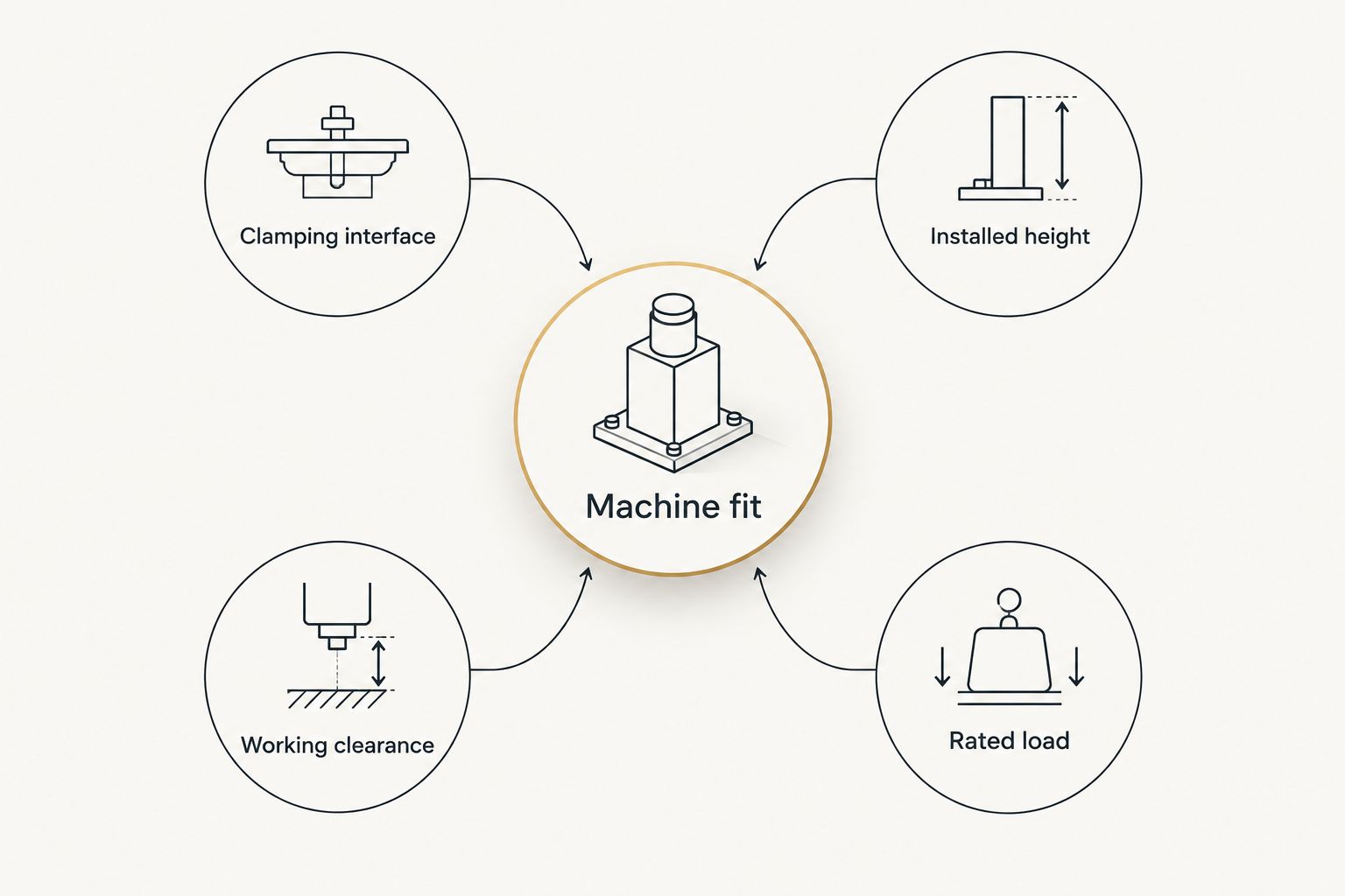
The installed height check must cover the assembled upper and lower tooling. Confirm the available opening, stroke and backgauge access for that stack, not merely for the bare machine.
- Supply machine model and upper and lower holder drawings.
- Verify tang geometry, seating and retention details.
- Record punch, die, holder and adapter heights.
- Check working clearance, stroke and backgauge access.
- Confirm ratings for every load-bearing component.
4. Simulate clearance through the entire bend sequence
Use a drawing overlay or your existing bending simulation to examine each bend. Check the part’s position before contact, during forming and during removal. A profile that reaches the bend line can still trap the completed part.
Straight punches suit geometry with unobstructed access; gooseneck profiles provide space for certain return flanges. Neither description proves clearance for your assembly. Compare the actual profile with the flange envelope, including the previous bends.
Sectional tooling helps configure working length and clearance for box-type parts, but the segment arrangement needs its own review. Verify extraction as carefully as forming. Operators must be able to remove the part using an approved sequence without defeating retention or creating an unsafe handling condition.
- Overlay punch and die profiles against every bend stage.
- Check return flanges against the punch body and holders.
- Verify segment lengths, joints and corner clearance.
- Check part support and backgauge contact at each stage.
- Confirm a safe removal path for the finished geometry.
5. Verify forming loads and surface contact
Calculate the required forming load using the material properties, thickness, bend length, die opening and forming method applicable to the job. Then compare that requirement with the machine, punch, die, holder and adapter ratings.
Check the rating basis: total force and force per unit length describe different limits. A short loaded segment must not be assessed solely against the machine’s total capacity. Follow the machine and tooling manufacturers’ requirements for permitted loading and tool placement.
Also inspect the die shoulders and punch contact surfaces. Burrs, embedded debris and damaged surfaces can transfer marks to the workpiece. For stainless work, use shop procedures that control contamination from carbon-steel debris; for protected surfaces, verify the actual contact arrangement by trial.
- Use an approved load calculation for the selected forming method.
- Verify total and local loading against documented ratings.
- Check load distribution and permitted tool positions.
- Inspect contact surfaces for damage, burrs and contamination.
- Qualify surface-protection methods before releasing production.
6. Separate ordinary bends from special forming
Review hems, offsets and other special features as distinct operations. Their contact geometry and load requirements differ from an ordinary air bend. Do not assign an air-bending load calculation to a closing operation without checking its applicability.
For a conventional pre-bend-and-close hem, document 2 forming stages: pre-bending and closing. Verify the required hem shape, material suitability, closing clearance and rated load at both stages. Flat and teardrop hems are different finished geometries, not interchangeable setup names.
A custom tool becomes relevant when standard profiles cannot satisfy the part geometry or an approved process requirement. Specify the required feature and constraints first; then request a drawing-based review of the proposed tool and process.
- Identify hems, offsets and features needing separate operations.
- Define pre-bend geometry and the finished hem section.
- Verify closing load and the complete tooling stack.
- Check access, part support and removal after special forming.
- Record the acceptance criteria for each formed feature.
7. Qualify the setup and preserve the revision
Inspect a representative formed part before releasing the setup. Measure the drawing’s controlling dimensions, radius and angles, and check the surfaces identified in the acceptance criteria. Confirm that the tested bend sequence matches the intended production sequence.
Keep 1 approved setup sheet for each qualified part-and-tooling combination. Record tool identification, segment arrangement, installed height, material condition, bend sequence and approved machine settings. A material or tool change requires review against that record rather than automatic reuse of the previous settings.
For a custom Chinacovo tooling request, provide the finished-part drawing, machine interface, material grade, thickness and required geometry together. Maintain the 2026 drawing and setup revisions through approval so the ordered tool, trial part and production setup refer to the same requirements.
- Measure first-piece angle, radius and controlling flange dimensions.
- Inspect exposed surfaces and joining areas.
- Record tool identities and the segment layout.
- Preserve approved settings and inspection results.
- Define which changes require renewed setup verification.
Compare tooling options by the part requirement
No tooling arrangement is best for every marine part. Standard tooling avoids commissioning a new profile when its geometry fits; custom tooling addresses defined constraints but requires a drawing-based engineering review. These options can overlap: a gooseneck punch can also be sectional.
| Option | Best for | Main advantage | Key limitation |
|---|---|---|---|
| Standard straight punch and V-die | Open profiles with unobstructed bend access | Straightforward setup when interface and geometry match | Punch body can interfere with previously formed flanges |
| Gooseneck punch | Return-flange geometry requiring relief around the punch | Provides clearance for suitable part envelopes | Actual profile, extraction path and load rating still require verification |
| Sectional punches and dies | Changing bend lengths and box-type parts | Allows segment arrangements around part geometry | Segment fit, joints and local loading need review |
| Dedicated hemming tooling | Parts requiring a specified folded-edge geometry | Provides tooling geometry for the approved hemming process | Pre-bend and closing requirements differ from ordinary air bending |
| Custom punches, dies or forming tools | Features that verified standard tooling cannot produce | Allows tooling design around the submitted part requirements | Requires detailed drawings, interface data and process qualification |
Chinacovo offers both standard and custom press brake tooling. The custom option is relevant when the review identifies a specific geometry or interface requirement; it does not eliminate the need to verify machine capacity, material behavior or first-piece results.
Common mistakes marine fabricators make
Treating all aluminum sheet as one forming specification
A shared thickness does not establish shared bendability. Record alloy, temper and rolling direction, then check the required radius against the supplied material rather than transferring a setup from an unrelated aluminum job.
Leaving weld and finish requirements out of tooling selection
A bend that meets its angle tolerance can still fail the part’s surface acceptance criteria. Mark exposed faces and joining areas on the drawing, and inspect those areas during tooling qualification.
Checking the first bend but not the closing bends
Return flanges change the available space as a part takes shape. Review the complete sequence, including backgauge contact, tool-body interference and removal; do not stop at a successful profile overlay for the first bend.
Approving capacity from the machine rating alone
The press brake is only one component in the load path. Check the punch, die, holders, adapters and segment loading against documented limits before approving the operation.
FAQ
What's the best press brake tooling for marine fabricators?
The best press brake tooling for marine fabricators is tooling verified against the finished-part drawing, material condition, machine interface and forming load. Use standard tooling when it satisfies those requirements; request custom engineering when a defined constraint remains.
Can I use the same tooling for marine aluminum and stainless steel?
The same tooling can serve both materials only when each setup satisfies its geometry, load and surface requirements. Verify material condition, die opening, radius and contamination controls separately rather than transferring the settings unchanged.
Does the punch nose radius determine the finished bend radius?
The punch nose radius alone does not determine the finished inside radius in air bending. Die opening and material behavior also affect the result, so qualify the required radius with the proposed setup.
Do I need a gooseneck punch for return flanges?
You need a gooseneck punch when its relief geometry solves an interference that a straight profile cannot clear. Check the actual punch profile, complete bend sequence, removal path and load rating before selecting it.
Will AMADA-style or WILA-style tooling fit my press brake?
A style name alone does not establish fit. Verify the clamping interface, tang, retention, seating surfaces, holders and installed height against your machine configuration.
What should I send Chinacovo for a custom tooling review?
Send Chinacovo the finished-part drawing, machine interface details, material grade, thickness and required geometry. Include bend length, radius, flange geometry, surface requirements and the proposed bend sequence.
How do I approve a marine press brake setup for production?
Approve the setup after a representative formed part meets the drawing and surface acceptance criteria using a verified tooling arrangement. Preserve the material condition, tool identities, segment layout, settings and inspection results in the approved setup record.
One last thing
Put the part-removal check on your 2026 setup approval sheet. Tool clearance during bending and clearance during extraction are different checks. A successful bend is not a complete process if the finished return flange traps the part around the punch.
Related guides
- Custom press brake tooling for OEM fabricators
- Press brake dies for stainless steel fabrication
- Segmented press brake dies for box forming
Open this COVO engineering guide · Browse press brake tooling · Request technical support