COVO KNOWLEDGE
Sheet metal gauge to thickness conversion benchmarks 2026
Published:
Updated:
Use a material-specific sheet metal gauge to thickness conversion chart. Compare steel, stainless and aluminum, then verify thickness before tooling review.

A sheet metal gauge to thickness conversion chart must identify the material: 16-gauge carbon steel is nominally 0.0598 in (1.519 mm), while the 16-gauge materials below range from 1.290 to 1.613 mm. This 2026 reference compares nominal dimensions for carbon steel, galvanized steel, stainless steel and aluminum, then explains what to verify before selecting press brake punches and dies.
- Use a material-specific sheet metal gauge to thickness conversion chart; gauge alone does not define thickness.
- 16-gauge carbon steel is 1.519 mm nominal; 16-gauge aluminum is 1.290 mm nominal.
- Chinacovo press brake tooling serves fabricators seeking standard or custom punches, dies and forming tools.
- Verify measured thickness, material grade, flange geometry and clamping interface before requesting a tooling review.
Why this matters
A gauge designation is a lookup reference, not a complete bending specification. Use this chart to translate the drawing, then carry the actual material dimensions into tooling selection. Chinacovo manufactures standard and custom press brake tooling; a gauge number alone does not define the required tool geometry.
Sheet metal gauge to thickness conversion chart: 2026 reference
The table gives nominal thickness, not allowable thickness variation. Each cell lists inches first and millimeters second; the overall row summarizes the selected gauge span rather than an average across unrelated material systems.
| Gauge | Carbon steel: in / mm | Galvanized steel: in / mm | Stainless steel: in / mm | Aluminum: in / mm |
|---|---|---|---|---|
| 10 | 0.1345 / 3.416 | 0.1382 / 3.510 | 0.1406 / 3.571 | 0.1019 / 2.588 |
| 12 | 0.1046 / 2.657 | 0.1084 / 2.753 | 0.1094 / 2.779 | 0.0808 / 2.052 |
| 14 | 0.0747 / 1.897 | 0.0785 / 1.994 | 0.0781 / 1.984 | 0.0641 / 1.628 |
| 16 | 0.0598 / 1.519 | 0.0635 / 1.613 | 0.0625 / 1.588 | 0.0508 / 1.290 |
| 18 | 0.0478 / 1.214 | 0.0516 / 1.311 | 0.0500 / 1.270 | 0.0403 / 1.024 |
| 20 | 0.0359 / 0.912 | 0.0396 / 1.006 | 0.0375 / 0.953 | 0.0320 / 0.813 |
| 22 | 0.0299 / 0.759 | 0.0336 / 0.853 | 0.0313 / 0.795 | 0.0253 / 0.643 |
| 24 | 0.0239 / 0.607 | 0.0276 / 0.701 | 0.0250 / 0.635 | 0.0201 / 0.511 |
| 26 | 0.0179 / 0.455 | 0.0217 / 0.551 | 0.0188 / 0.478 | 0.0159 / 0.404 |
| Overall selected span: gauges 10–26 | 0.0179–0.1345 / 0.455–3.416 | 0.0217–0.1382 / 0.551–3.510 | 0.0188–0.1406 / 0.478–3.571 | 0.0159–0.1019 / 0.404–2.588 |
At 16 gauge, galvanized steel is the thickest listed material at 1.613 mm; aluminum is the thinnest at 1.290 mm. Across the entire selected table, 10-gauge stainless steel has the largest nominal thickness at 3.571 mm, while 26-gauge aluminum has the smallest at 0.404 mm. These are dimensional comparisons, not rankings of strength or suitability for bending.
Source and methodology: Engineers Edge, Sheet Metal Gauge Size Chart, an undated public reference table for nominal U.S. sheet-metal gauge dimensions, used here as a 2026 reference; millimeters are calculated from the listed inches using exactly 25.4 mm per inch and rounded to three decimal places. Limitation: the table does not establish a supplier's thickness tolerances, alloy properties or the measured thickness of your sheet.
How to use these benchmarks
Use the chart as a translation step between the drawing and the material specification. For 2026 tooling reviews, keep nominal gauge values separate from measured dimensions and drawing tolerances.
- Choose the material column before the gauge row. At 18 gauge, carbon steel is 1.214 mm and aluminum is 1.024 mm. Entering the steel value for an aluminum part changes the dimensional basis of the setup before you evaluate radius or load.
- Keep a declared unit system through the review. The 16-gauge carbon-steel entry is 0.0598 in, converted to 1.519 mm. Do not treat the rounded metric display as a separately specified stock thickness or a tolerance limit.
- Measure stock before releasing the setup. The 20-gauge stainless entry is 0.953 mm nominal. Record the measured thickness and compare it with the purchase specification; the chart does not determine whether that sheet is acceptable.
- Do not select tooling from thickness alone. The 14-gauge galvanized entry is 1.994 mm nominal, but die opening, punch radius, flange geometry, bend length and rated load still need verification against the actual job.
A chart value belongs in the preliminary material record. The production record should also identify the material grade, governing specification and measured thickness so another engineer can reproduce the selection without interpreting a gauge label.
What the material columns do—and do not—tell you
The same gauge number does not create an interchangeable material specification. Changing the material requires a new dimensional and forming review, even when the drawing retains the same gauge designation.
| Material reference | Best for | Useful feature | Limitation to verify |
|---|---|---|---|
| Carbon steel column | Translating a carbon-steel gauge callout | Gives a nominal dimension for the stated gauge system | Does not identify grade, strength or permitted variation |
| Galvanized steel column | Translating a galvanized-sheet gauge callout | Keeps the galvanized reference distinct from uncoated steel | Does not specify coating designation or supplier tolerances |
| Stainless steel column | Translating a stainless-sheet gauge callout | Prevents substitution of carbon-steel gauge dimensions | Does not identify stainless grade or forming condition |
| Aluminum column | Translating an aluminum-sheet gauge callout | Shows the aluminum-specific nominal thickness | Does not identify alloy, temper or rolling direction |
At 14 gauge, galvanized steel is listed at 1.994 mm and stainless steel at 1.984 mm. Their close nominal dimensions do not establish equivalent bending behavior. Grade, condition and the required finished-part geometry remain separate inputs.
At 10 gauge, stainless steel is listed at 3.571 mm and carbon steel at 3.416 mm. The table establishes that dimensional difference only. It does not provide a valid load comparison without additional material and setup information.
For coated material, record whether the governing thickness specification refers to the substrate or the finished coated sheet. Do not infer that distinction from the gauge label. Use the material purchase specification and the supplier's dimensional documentation to resolve it.
Verification sequence before choosing press brake tooling
Start with the finished-part drawing, not the closest available punch. Chinacovo press brake tooling includes standard and custom punches, dies, forming tools and accessories; the engineering review should connect the required geometry to the material and machine interface.
Material grade
Identify the metal family and exact grade or alloy. For aluminum, include temper; for coated sheet, include the coating designation required by the job. A description such as steel sheet leaves information unresolved even when the nominal thickness is known.
Actual thickness
Measure the material with an appropriate calibrated instrument and record the measurement method. Check representative locations according to the applicable inspection procedure, avoiding burrs and damaged edges. Keep the nominal chart value and the measured result in separate fields.
Part geometry
Provide the finished angle, inside radius, flange dimensions and bend length. Include return flanges, hems, offsets and features that restrict tool access. State whether the drawing dimensions apply before or after forming, and identify the revision used for the review.
Machine interface
Verify the upper clamping interface, lower holder, retention features and installed height. Identify the machine and existing holder configuration rather than treating a machine brand as a complete interface specification. Confirm that the proposed tool arrangement fits the actual machine configuration.
Load review
Check the required forming load against the applicable machine, punch, die, holder and segment ratings. Include bend length and the proposed forming method. A thickness conversion establishes neither a permissible tool load nor a safe setup.
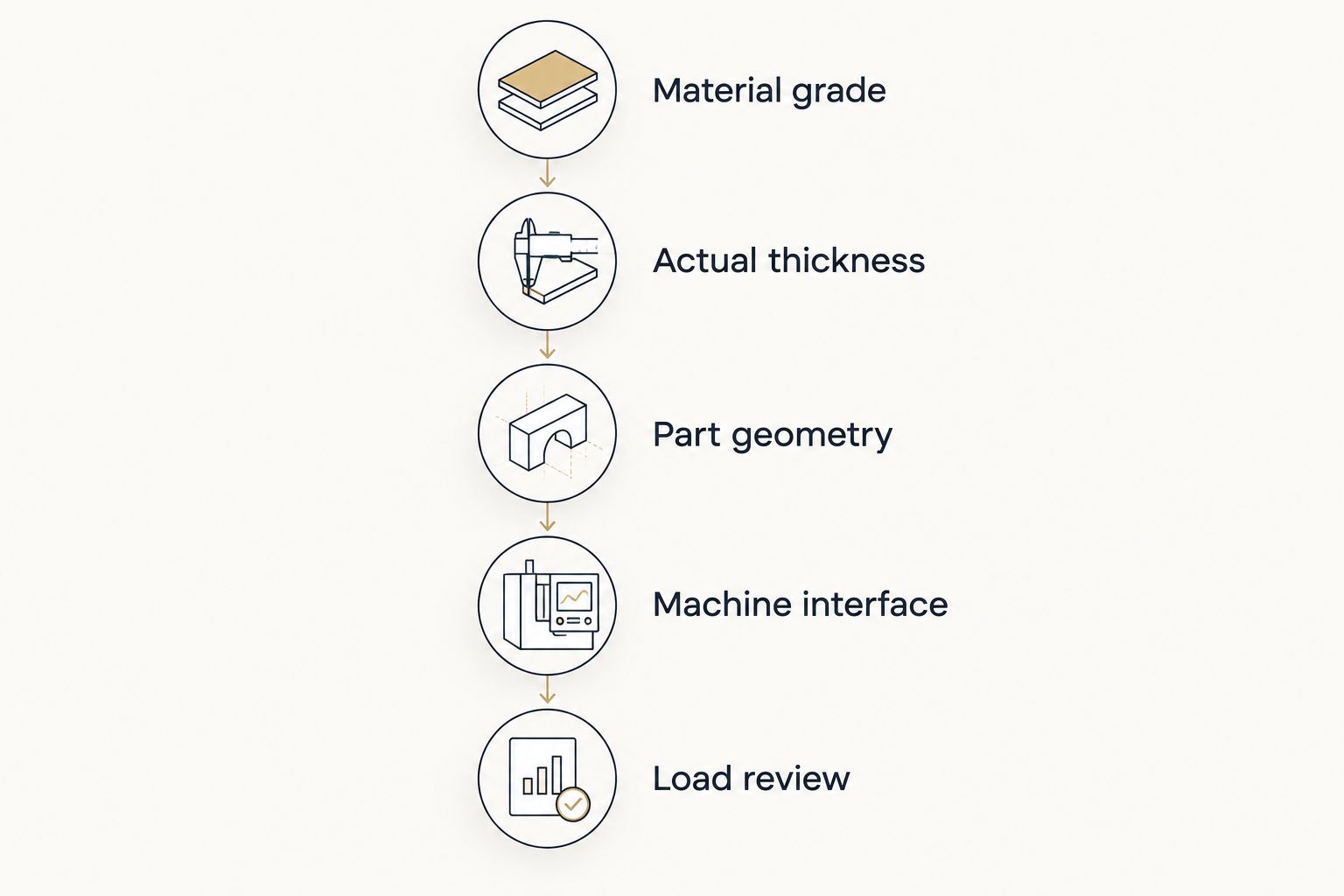
Keep these checks together in the tooling request. A correct gauge conversion cannot resolve a conflicting radius, an inaccessible return flange or an unmatched clamping interface. Resolve those constraints before approving the tool drawing.
Worked example: a 16-gauge drawing callout
Suppose a drawing specifies 16-gauge sheet but does not identify the material family. The chart gives carbon steel at 1.519 mm, galvanized steel at 1.613 mm, stainless steel at 1.588 mm and aluminum at 1.290 mm. Do not release a thickness-dependent setup until the material specification is resolved.
If the job specifies carbon steel, use 0.0598 in as the nominal gauge reference. Then compare the measured stock with the purchase specification and its permitted variation. Do not reject or approve the material solely because a measurement differs from the rounded 1.519 mm display.
For the bending review, add the grade, required inside radius, flange geometry and bend length. Check the proposed punch and die arrangement against the machine interface and installed height. This sequence turns a gauge label into a traceable setup specification without treating the chart as a tooling approval.
The 2026 reference table is useful for interpreting the drawing; it does not replace the drawing. If the drawing also gives a numeric thickness that conflicts with the gauge reference, ask for clarification from the responsible engineering authority rather than silently choosing one value.
Prepare a custom tooling review package
Chinacovo is best suited to sheet-metal fabricators seeking standard or custom press brake punches, dies and forming tools. For a custom review, supply the finished-part drawing together with the machine interface, material grade, thickness and required geometry. The benefit is a part-specific engineering discussion; the limitation is that a gauge designation alone cannot define the tool.
Use this submission checklist:
- Drawing: current revision, finished-part dimensions, angle and radius requirements, plus critical flange geometry.
- Material: grade or alloy, condition or temper where applicable, nominal thickness, measured thickness and governing tolerances.
- Bending setup: intended forming method, bend sequence, bend length and any existing punch or die constraints.
- Machine: model, clamping interface, lower holder details, installed height requirements and relevant capacity documentation.
- Access constraints: return flanges, box walls, adjacent features, segment arrangement and removal clearance.
- Surface requirements: permitted marking, protective finish requirements and any restrictions relevant to tool contact.
Include drawings or dimensions of the existing interfaces when replacing tooling. A machine name does not describe every installed holder or adapter. Review segment fit, clamping and loads before requesting approval of a replacement arrangement.
Prepare your tooling review
Compare custom tooling considerations after verifying material, part geometry and machine interface.
Where gauge conversion stops being useful
Gauge is convenient for interpreting an established drawing convention. It is less useful when the engineering decision requires an explicit dimension, tolerance or material property. Keep the original callout for traceability, but use specified and measured dimensions in the setup record.
Do not interpolate a gauge number to create a material specification. A metric thickness listed on a drawing remains that specified thickness; an approximate gauge equivalent is only a reference. Use the applicable drawing requirements and material specification to determine acceptance.
Likewise, do not read extra accuracy into the displayed decimal places. The conversion factor is exact, but converting a nominal inch value to three decimal places in millimeters does not establish the precision of the supplied sheet. Nominal values and manufacturing tolerances answer different questions.
For a 2026 job traveler, record the chart source separately from the material inspection result. That distinction lets purchasing trace the intended gauge convention and lets production verify the actual stock. Neither record substitutes for the other.
FAQ
How thick is 16-gauge sheet metal?
16-gauge carbon steel is nominally 0.0598 in, or 1.519 mm. The same gauge is 1.613 mm for galvanized steel, 1.588 mm for stainless steel and 1.290 mm for aluminum in this reference table.
Is a higher sheet metal gauge thicker or thinner?
A higher gauge number means thinner sheet within each material system shown here. Carbon steel decreases from 3.416 mm at 10 gauge to 0.455 mm at 26 gauge; compare gauges within the same material column.
Can I use a steel gauge chart for aluminum?
No, use the aluminum column for an aluminum gauge callout. At 18 gauge, carbon steel is 1.214 mm while aluminum is 1.024 mm, so substituting the steel value changes the nominal dimension.
How do I convert sheet thickness from inches to millimeters?
Multiply the inch thickness by exactly 25.4 to obtain millimeters. This chart rounds the metric results to three decimal places; that rounding does not define the material tolerance.
Does a gauge conversion chart include sheet thickness tolerances?
No, this chart provides nominal dimensions only. Obtain allowable variation from the governing material specification, purchase requirements and supplier documentation, then compare the measured stock against those requirements.
Can I choose a press brake die from the gauge number alone?
No, gauge alone is insufficient for press brake die selection. Verify actual thickness, material grade, bend length, required radius, flange geometry, machine interface and the applicable load ratings.
What should I send Chinacovo for a custom press brake tooling review?
Send the finished-part drawing, machine interface details, material grade, thickness and required geometry. Include bend length, flange clearance, installed height requirements and existing tooling constraints so the review addresses the complete setup.
One last thing
A gauge conversion can be correct while the tooling request remains incomplete. The overlooked item is often not another thickness decimal; it is an unresolved drawing or setup requirement. Check whether the inside radius is mandatory, whether the flange dimension allows the intended forming method and whether the part clears the tool throughout the bend sequence.
Before releasing the request, place the material specification beside the finished-part drawing and the machine-interface information. Each should describe the same job revision. That final cross-check is more useful than replacing a measured thickness with the chart's nominal value.
Related guides
- Custom press brake tooling for OEM fabricators
- Press brake dies for thin-gauge sheet metal
- Press brake dies for stainless steel fabrication
- Segmented press brake dies for box forming
Open this COVO engineering guide · Browse press brake tooling · Request technical support