COVO KNOWLEDGE
BendPilot to finished bend program: complete 2026 workflow
Published:
Updated:
BendPilot press brake planning needs verified tooling before release. Check interfaces, installed height, loads, bend sequence and first-piece inspection.
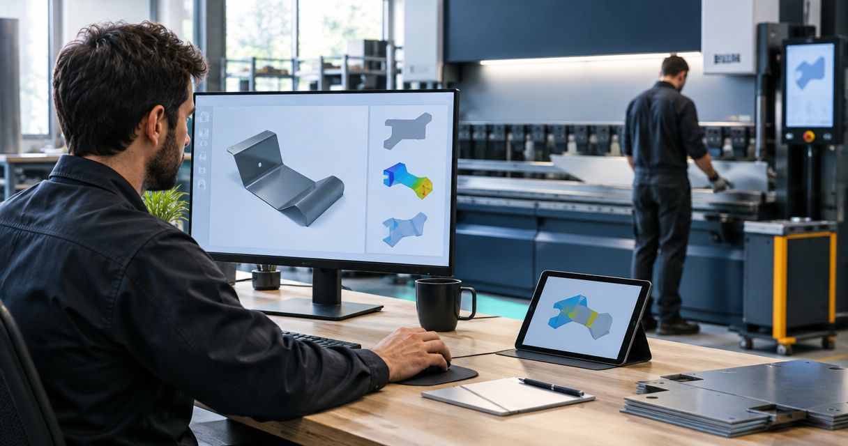
Instead of manually rebuilding tooling assumptions for every bend, use a verification-led BendPilot press brake planning workflow that connects the finished-part drawing, machine configuration, tooling geometry and prove-out record. A finished bend program is ready for production only after its assumptions match the installed setup and the inspected part.
- BendPilot press brake planning needs verified part, machine and tooling inputs before production release.
- Chinacovo manufactures standard and custom press brake tooling; request engineering review when finished-part geometry requires it.
- Check clamping interface, installed height, bend length and rated loads before accepting a tooling arrangement.
- Release the bend program with its setup sheet and first-piece inspection record, not as an isolated file.
Why this matters
A planned bend sequence and a usable machine setup are different deliverables. The sequence describes how to form the part; the setup must also establish that the selected punches, dies, holders and backgauge arrangement fit the actual machine and workpiece.
Chinacovo press brake tooling is best for fabricators specifying standard or custom punches and dies against finished-part and machine requirements. Use the custom press brake tooling guide for OEM fabricators when the drawing requires a profile that your existing tooling cannot satisfy.
For your 2026 workflow, keep planning approval separate from production approval. A geometrically acceptable plan still needs load verification, physical setup checks and an inspected first piece. Do not let a successful file transfer substitute for those checks.
Before you start
- Part and material records: Obtain the released finished-part drawing, relevant model, material grade, thickness, grain-direction requirements, bend radii, flange dimensions, tolerances and surface requirements. Identify the drawing revision before selecting tooling.
- Machine and planning access: Have authorized access to the installed BendPilot environment, its version-specific documentation, the press brake documentation and the approved program-transfer procedure. Record the machine configuration, controller, holders, adapters, backgauge arrangement and applicable load limits.
- Tooling records and the hidden gotcha: Obtain dimensioned punch and die drawings, segment lengths, retention details and manufacturer load ratings. A compatible clamping interface does not establish compatible installed height or clearance: include every holder and adapter in the assembled geometry before planning the sequence.
Use the engineering record labels below as worksheet headings, not as software menu names. Select software commands from the documentation for your installed version, and follow the machine manufacturer's setup and safety procedures throughout.
Part definition and planning inputs
- Establish the drawing baseline. Record Part revision, Material grade, Thickness, Inside radius, Flange geometry and Surface requirements. Distinguish nominal dimensions from acceptance tolerances, and identify dimensions measured after forming rather than on the flat blank.
- Check the model against the drawing. Compare bend locations, flange orientation, holes near bends, corner reliefs and any forming details. Resolve conflicts before using the model as the planning reference; do not silently replace the released drawing with an older model.
- Verify the flat-pattern basis. Identify the approved bend allowance or bend deduction method and the assumptions behind it. Keep material thickness, forming method and tooling geometry consistent with that basis. Record who approves changes when the developed blank needs correction.
- Set units and acceptance criteria. Keep dimensional units consistent across the part, tooling and machine records. Identify whether force is expressed as total force or force per unit length; kN and kN/m describe different quantities. Record the inspection method for each critical angle, flange and radius.
Expected result: You have one controlled part definition with an identifiable revision and explicit acceptance criteria. The planning record points to the same drawing that production and inspection will use.
For a 2026 release record, identify the revision rather than relying on a filename containing the current year. A year label organizes documents; it does not tell the operator which geometry is approved.
Machine configuration and tooling arrangement
- Identify the actual machine. Record Machine configuration, Clamping interface, Holder arrangement and Backgauge arrangement. Verify these against the installed equipment, including adapters and optional equipment that change available space. Do not substitute a machine-family name for a configuration check.
- Describe the complete tool assembly. Record punch profile, die opening, working angles, tip radius, tool heights and mounting features from dimensioned drawings. Include holder and adapter geometry when establishing Installed height. Check retention and seating requirements against the applicable machine and tooling documentation.
- Match segments to the part. Record Bend length and Segment arrangement. Check that the proposed arrangement supports the bend and leaves clearance for adjacent flanges. Identify segment joints and the relationship between the bend location and the tool arrangement.
- Verify loads before approving the setup. Determine the required bending load using an approved method for the material, thickness, bend length and forming process. Compare it with the applicable machine, punch, die, holder and adapter ratings. Check both total load and local loading restrictions.
Expected result: The plan describes a physical assembly, not just a punch name and die opening. Every component has an identified geometry, mounting arrangement and applicable load rating.
For a BYSTRONIC-equipped setup, use the BYSTRONIC press brake tooling connection guide to organize interface checks. The machine name alone does not establish fit.
Standard tooling or custom tooling?
Choose the tool route from the finished-part requirements. Chinacovo manufactures both standard and custom press brake punches, dies and forming tools; the selection still needs an engineering check against your machine and part.
| Tooling route | Best for | Advantage | Limitation | Verification before planning |
|---|---|---|---|---|
| Standard tooling | Parts that fit a documented existing profile | Lets you plan around an established tool drawing | Existing geometry can restrict flange clearance or the required forming operation | Interface, radius, opening, installed height, segment arrangement and loads |
| Custom tooling | Parts requiring geometry that standard profiles cannot provide | Allows the tool design to address the specified finished-part geometry | Requires additional engineering definition and verification | Finished-part drawing, machine interface, material, thickness, geometry and load case |
Use standard tooling when it satisfies the complete requirement; request custom engineering when a defined requirement remains unresolved. Custom tooling is not a substitute for checking the bend sequence or the machine's limits.
Bend sequence and clearance verification
- Build the sequence around access. Identify which bends restrict access to later bends. Review the workpiece orientation at each operation, including the space needed to insert, position and remove the part. Check return flanges and enclosed features before accepting the sequence.
- Define the gauging arrangement. Record Gauge surfaces, Part orientation and Support method for each operation. Confirm that the selected reference surface exists at that stage and can contact the intended gauge. Avoid planning around a flange that has already moved or become inaccessible.
- Check the full clearance envelope. Review the part against the punch body, die, holders, adapters, machine structure and backgauge components. Where documented checking functions exist in your installed environment, use them with verified geometry. Supplement them with the approved engineering review; an incomplete model cannot verify omitted components.
- Review handling and forming requirements. Identify operations needing a changed orientation, different tooling station or separate forming setup. Check hemming and other special forming operations against their own geometry and load requirements. Follow the manufacturer's procedures for any machine movement used during verification.
Expected result: Each bend has a documented orientation, gauging reference, tooling arrangement and clearance check. The operator can understand how the part moves through the sequence without reconstructing the planner's intent.
The sequence review should follow the same order as the physical work: establish the part, verify the assembly, review movement, then prove the setup. This prevents a downstream clearance problem from being treated as a minor program edit.
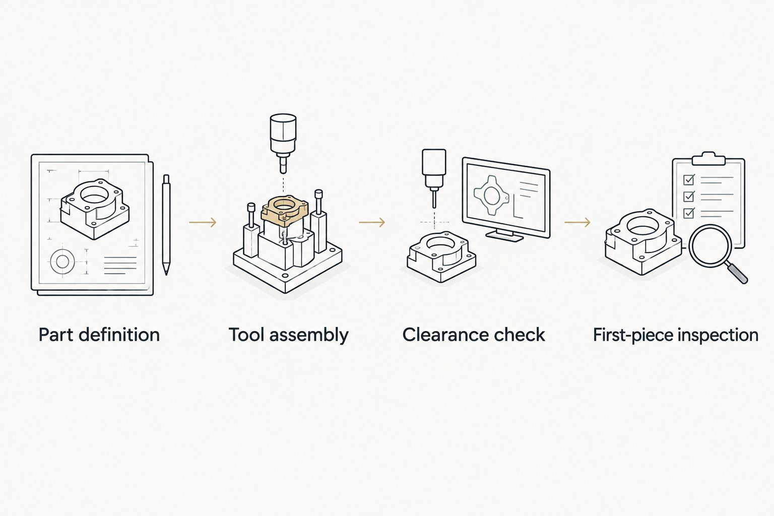
Preserve the planning assumptions
Attach the tooling drawings and setup arrangement to the planning record. A tool description without its geometry is not enough to reproduce a clearance review. Record any deliberate deviations from the original plan and obtain the required approval before release.
For 2026 production records, distinguish planned, verified and released status. These are engineering record labels: they prevent an unproved arrangement from being mistaken for an approved production setup.
Program transfer and first-piece release
- Verify the controller handoff. Confirm the documented output and transfer requirements for the installed planning environment and controller. Use only the approved procedure. Check that the receiving machine, program identity and part revision match the intended job before loading the program.
- Issue the setup record. Include the tool assembly, segment layout, installed height reference, bend sequence, gauging instructions and handling requirements. Identify the tooling physically so that similar-looking profiles are not treated as interchangeable.
- Verify the installed setup. Have authorized personnel check seating, retention, alignment, segment arrangement and the applicable operating limits. Perform the manufacturer's prescribed setup verification. Do not improvise a clearance test by bypassing guards or placing hands inside the working area.
- Inspect and release the first piece. Measure the drawing's critical angles, flange dimensions, radii and other specified features. Record approved corrections and their reasons. Release the program together with the setup sheet and inspection record only after the part meets the acceptance criteria.
Expected result: The released program is tied to an inspected part and a reproducible physical setup. The record identifies the machine, tooling, material and drawing revision used for approval.
Do not release a program solely because the controller accepts it. File acceptance establishes that the controller received a usable file; it does not establish conformity of the finished part.
Revalidate whenever the drawing or setup changes
The adjacent workflow is change-controlled replanning. Use it whenever the drawing revision, material, thickness, tooling assembly or machine configuration changes; do not assume the previous approval covers the changed condition.
- Compare the revised requirement with the last released record.
- Identify affected bends, tooling geometry, loads, gauging references and clearance checks.
- Repeat the relevant planning and setup verification steps.
- Inspect the changed part and issue an updated release record.
Keep the prior release traceable. Do not overwrite the evidence that explains how an earlier revision was produced. For repeat jobs in 2026, compare the current physical setup with the released record before reusing a program.
A tooling substitution needs the same discipline. Matching the die opening while changing die height, punch profile or holder arrangement changes the assembly being verified, even when the part drawing remains unchanged.
Troubleshooting
- The proposed tool fits the clamp but the part interferes. Recheck installed height and the complete assembly envelope. Include holders, adapters, punch body and already formed flanges; then revise the profile or sequence through engineering review.
- The part cannot reach the planned gauge surface. Review the workpiece at that specific operation. Select an accessible reference, revise the orientation or change the sequence, and verify the replacement gauging arrangement before production.
- The first piece misses angle or flange tolerances. Separate angle error from developed-length error. Verify material, thickness, seating, tooling geometry and the flat-pattern basis before applying corrections under the approved process.
- The program cannot be used by the intended controller. Check the documented output requirements, selected machine configuration and approved transfer procedure. Resolve the mismatch before machine setup; renaming a file does not establish controller compatibility.
- An approved job changes after a tooling substitution. Compare the replacement assembly with the released tool drawings. Recheck interface, installed height, radius, die geometry and load ratings, then repeat the affected inspections.
Customize your workflow
Expand the setup record with the evidence your jobs actually require. Add surface-protection instructions for cosmetic parts, segment-layout references for boxes, and separate forming records for hemming or other special operations.
When requesting Chinacovo custom tooling review, supply the finished-part drawing, machine interface details, material grade, thickness and required geometry. Include the existing tool assembly and the specific interference or forming requirement you need resolved. A defined constraint gives the engineering review a clear task.
For your 2026 document template, keep approval responsibilities explicit. Identify who controls the drawing, who verifies the tooling arrangement and who authorizes production release; avoid treating all three as an unnamed planning task.
FAQ
What is the safest way to use BendPilot press brake planning?
Use BendPilot press brake planning within a documented process that verifies the part, machine, tooling, loads and first piece. Follow the installed software documentation and the machine manufacturer's setup and safety procedures.
Can I run a bend program as soon as it transfers to the machine?
No; program transfer does not establish that the installed tooling or finished part is correct. Verify the physical setup and inspect the first piece before production release.
What tooling information do I need before planning bends?
You need dimensioned punch and die geometry, clamping and retention details, tool heights, segment arrangements and applicable load ratings. Include holders and adapters when checking installed height and clearance.
Is standard tooling better than custom tooling?
Standard tooling is the appropriate route when its documented geometry satisfies the part and machine requirements. Custom tooling addresses a defined requirement that the standard arrangement cannot meet, but still needs load, interface and sequence verification.
What should I send Chinacovo for a custom tooling review?
Send the finished-part drawing, machine interface details, material grade, thickness and required geometry. Include the proposed or existing assembly and identify the clearance, radius, flange or forming requirement that needs review.
Do I need to recheck a bend program after changing the punch?
Yes; changing the punch changes the tooling assembly covered by the original approval. Compare its geometry, installed height, mounting details and load rating, then repeat the affected setup and part checks.
How do I know the finished bend program is ready for repeat production?
The program is ready when its release record includes an approved setup and an inspected conforming part. Before repeating the job, confirm that the current drawing, material, machine and tooling match that record.
One last thing
Record the assembled tooling height, not only the individual punch and die heights. A holder or adapter change can alter the physical setup without changing the tool names on the setup sheet. Preserve the assembly drawing with the released program so the next operator verifies the same geometry.
Related guides
- WILA clamping system interface checks
- Segmented press brake dies for box forming
- Press brake tooling for electrical enclosures
Open this COVO engineering guide · Browse press brake tooling · Request technical support