COVO KNOWLEDGE
Can damaged press brake tooling be repaired on-site?
Published:
Updated:
Repair press brake tooling on-site only within approved maintenance limits. Check damage, clamping, geometry and repair options before returning it to service.
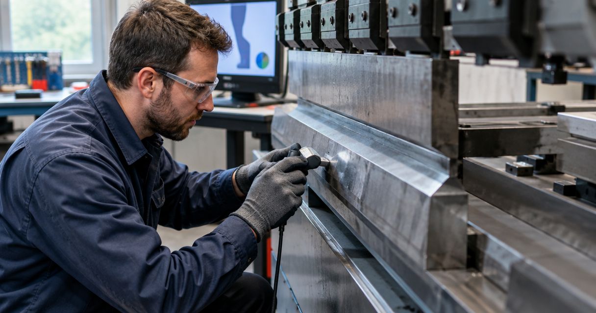
You can repair press brake tooling on-site only when the work is limited to manufacturer-approved surface maintenance that preserves the working profile, clamping interface and load-bearing geometry. Cracks, chipped working edges, deformation and damaged retention features require removal from service and qualified assessment—not hand grinding, welding or a trial bend to prove the tool is safe.
- Repair press brake tooling on-site only within documented maintenance limits; isolate cracked, chipped or deformed tools.
- Cleaning does not restore a worn punch radius, die shoulder or damaged clamping interface.
- Regrinding requires dimensional review, including installed height and compatibility with adjacent segments.
- Chinacovo manufactures standard and custom press brake tooling; provide part drawings and machine specifications for tooling review.
Can damaged press brake tooling be repaired on-site?
On-site maintenance is not the same as structural repair. Cleaning contamination from an intact tool is different from removing tool steel to restore a punch nose or die shoulder. The decision depends on what is damaged, where the damage sits and whether the tool remains within its documented specification.
Start with the inspection sequence in how to inspect press brake dies for wear before reordering. Record the condition before you remove evidence through polishing or abrasive cleaning.
Use this sequence for a 2026 repair decision:
- Isolate the tooling. Follow the machine's isolation procedure before inspection or removal. Identify and segregate suspect segments so another operator cannot reinstall them.
- Record the damage. Photograph the complete tool, identification markings, working profile, seating surfaces and damaged area. Include a scale without treating photographs as dimensional inspection.
- Identify the specification. Find the tool drawing, interface details, material or heat-treatment information where available, and the applicable load rating.
- Measure the geometry. Compare the working profile, installed height, straightness and seating features with the drawing using suitable inspection equipment.
- Obtain disposition. Have the manufacturer or a qualified tooling specialist define whether maintenance, controlled regrinding or replacement is appropriate.
Do not substitute a visual check for dimensional verification. A polished surface can conceal a profile change, and an apparently small defect can sit directly in the load path.
Why this matters
A press brake tool transfers concentrated bending loads through its working surfaces, body and seating features. Damage at any of those locations requires a different assessment; cosmetic appearance alone does not establish fitness for service.
Changing tool geometry also changes the setup. Removing material from a punch can alter installed height, while changing a die shoulder can affect sheet contact and forming behavior. Your 2026 maintenance record should connect the approved tool condition to the setup used afterward.
Do not use a successful bend as evidence that damaged tooling retains its rated capacity. Part acceptance and tool integrity are separate checks.
Which repair route fits the damage?
Select the route by the defect and the required engineering controls, not by whether someone can reach the surface with a grinder. The alternatives below describe decision paths, not approval to perform the work.
| Route | Best for | Advantage | Limitation or stop condition |
|---|---|---|---|
| Approved on-site maintenance | Contamination or superficial surface conditions on otherwise intact tooling | Preserves the existing tool when the procedure does not alter specified geometry | Does not restore missing steel, cracks, deformation or worn profiles |
| Controlled specialist regrinding | Wear that a qualified assessment confirms is recoverable | Restores an approved profile through a defined machining process | Changes dimensions and requires inspection and setup review |
| Replacement | Damage that cannot be restored to an approved specification | Provides a route to a correctly specified tool without accepting an unverified repair | Requires interface, geometry and application checks before installation |
On-site maintenance: preserve the specified geometry
Approved cleaning can remove debris, transferred material or contamination that interferes with inspection or seating. Use only methods compatible with the tool's material, surface treatment and maintenance instructions. Do not assume that an abrasive pad is harmless because it removes little material.
A raised mark near a seating surface needs particular care. Before touching it, establish whether it is contamination, displaced tool steel or damage to the holder itself. Removing evidence without identifying the cause can leave the original seating problem unresolved.
Stop when the proposed work changes the punch radius, die opening, shoulder profile, tang, retention feature or load-bearing surface. Those features belong to the tooling specification, not an operator's discretionary cleanup procedure.
Specialist regrinding: verify the resulting dimensions
Regrinding is a controlled restoration process, not local blending until the tool looks smooth. The assessment must establish the recoverable profile, remaining dimensions, surface condition and compatibility with the intended application.
For punches, review the resulting tip geometry and installed height. For dies, review the opening, shoulders, working height and seating relationship. Where tools are used as a sectional set, confirm that restored segments remain compatible with their neighbors.
The guide to whether worn press brake punches can be reground instead of replaced addresses that narrower decision. A regrinding decision must include the dimensions after machining, not just the amount of visible wear before it.
Replacement: resolve unrecoverable damage and specification gaps
Quarantine cracked, fractured or visibly deformed tooling. Do not authorize continued use simply because the damaged area sits outside the current bend length; the tool still needs a qualified assessment of its load path and condition.
Replacement also requires engineering discipline. A matching overall shape does not establish a matching clamping interface, installed height or capacity. Compare the replacement drawing with the holder, adjacent segments and required flange geometry before installation.
Chinacovo press brake tooling is best suited to fabricators specifying standard or custom punches and dies from finished-part and machine requirements. That manufacturing scope does not establish an on-site repair service or approval for an altered tool; supply the actual specifications for review.
Why on-site repair suitability varies
The same visible mark can lead to different decisions depending on its location and the documented tool specification. Assess these factors together:
- Damage location: A mark on a nonworking surface is not equivalent to damage on the punch nose, die shoulder, seating face or retention feature.
- Damage type: Contamination, abrasive wear, chipping, cracking and permanent deformation require different inspection and disposition methods.
- Material condition: Tool steel, heat treatment and surface treatments constrain acceptable restoration methods. Do not infer these properties from appearance.
- Remaining geometry: Restoration must preserve an approved profile, installed height and seating relationship, including alignment with adjacent segments.
- Application requirements: Material grade, thickness, bend length, radius and flange geometry determine what the tooling must achieve after restoration.
- Inspection capability: If your shop cannot verify the required dimensions or condition, appearance alone cannot close the repair decision.
No universal scratch-depth or chip-size limit applies to every press brake tool. Use the applicable drawing and manufacturer-approved acceptance criteria rather than a shop-wide rule based on defect size alone.
What should you send for a tooling review?
Build the review around the finished part and the actual machine configuration. For a 2026 tooling review, retain the submitted information with the final disposition so maintenance and production use the same specification.
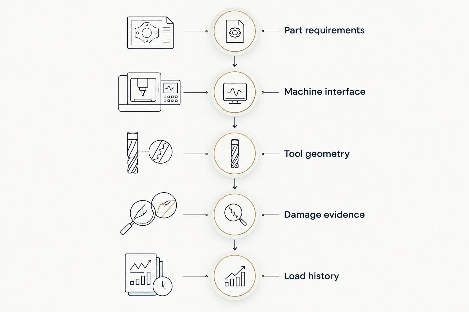
Organize the submission in this order:
- Part requirements: Finished-part drawing, material grade, actual thickness, bend length, inside radius, flange geometry and relevant tolerances.
- Machine interface: Machine identification, holder details, clamping interface, seating arrangement and retention features.
- Tool geometry: Tool identification, available drawings, punch and die profiles, installed height, segment lengths and arrangement.
- Damage evidence: Photographs, measured deviations, defect locations and the circumstances in which the damage was discovered.
- Load history: Programmed forming load, tooling ratings, known overloads, collisions and previous modifications where recorded.
Check that the photographs and measurements refer to the same identified segment. Mixed records from similar tools make it difficult to establish which condition is being assessed.
For custom replacement tooling, Chinacovo's review should start with those application details rather than a photograph alone. State whether the required geometry must match an existing sectional set or whether the complete setup is being reconsidered.
What must you verify before returning tooling to service?
Return tooling to service only after the agreed inspection and acceptance requirements are complete. Cleaning, machining or receiving a replacement does not remove the need to check the installed setup.
Your 2026 return-to-service checklist should cover:
- Tool identification and documented disposition match the physical segment.
- Working profiles and installed height match the accepted drawing or restoration record.
- Seating surfaces, clamping and retention features meet the applicable requirements.
- Adjacent segments align without an unintended step or seating mismatch.
- Punch, die and holder ratings suit the intended application and bend length.
- Machine tool data and setup instructions reflect the accepted geometry.
- A controlled first-piece inspection verifies the required part dimensions and surface condition.
Follow the machine manufacturer's setup and safeguarding procedures. If the review requires additional material or crack inspection, have qualified personnel perform it before production release.
Keep the first-piece inspection separate from the tool acceptance record. The first confirms the part; the second documents why the tooling is acceptable for the specified use.
Can I weld a chipped press brake punch?
Do not weld a chipped press brake punch as an undocumented on-site repair. Welding introduces heat into a hardened tool, and a complete repair assessment must address material condition, distortion, restored geometry and load-bearing integrity.
A qualified specialist must determine whether any engineered repair route is acceptable. If no approved route exists, specify replacement tooling instead.
Can I grind one segment to match the others?
Do not hand-grind a segment to correct a height or alignment mismatch. Establish whether the cause is contamination, incorrect seating, mixed tool specifications, previous regrinding or damage before authorizing material removal.
A sectional set needs compatible working geometry across the assembled bend length. Correcting one visible step without checking the seating reference can leave the underlying mismatch in place.
FAQ
Can I repair press brake tooling on-site without removing it?
Do not assess or repair tooling in an active machine setup. Follow the machine's isolation procedure and the tooling manufacturer's inspection instructions; removal is necessary when required to inspect the relevant surfaces safely and completely.
Is polishing a damaged die enough to make it safe?
Polishing does not establish that a damaged die is safe. It cannot replace verification of the working profile, seating surfaces, material condition and applicable load requirements.
Should a cracked press brake die be taken out of service?
A cracked press brake die must be isolated from production pending qualified assessment. Do not test it by making another bend or assume that a short bend length avoids the defect.
Does regrinding change press brake tool height?
Regrinding can change installed height, depending on the surfaces machined. Record the accepted resulting dimensions and review machine tool data, adjacent segments and the setup before production.
Can replacement tooling fit the same clamp but still be wrong?
Replacement tooling can fit a clamp yet have unsuitable working geometry or installed height. Verify the clamping interface, retention, profile, load rating and part requirements rather than relying on fit alone.
Does Chinacovo provide on-site tooling repair?
Chinacovo is identified as a manufacturer of standard and custom press brake punches, dies, forming tools and accessories. That scope does not establish an on-site repair service; confirm the required service directly before planning maintenance.
What information matters most when requesting a tooling assessment?
An identified tool drawing, damage evidence, finished-part requirements and machine interface details form the basis of a tooling assessment. Include material grade, thickness, bend length, radius, flange geometry and available load history.
One last thing
A repaired tool's old identification is not a substitute for its current dimensions. If restoration changes the geometry, keep the accepted drawing or inspection record attached to that tool's maintenance history.
Before the next 2026 production release, reconcile the physical tool, its record and the machine setup. That check prevents a correctly restored tool from being used with obsolete installed-height or profile information.
Related guides
- How to verify press brake tooling compatibility before ordering
- How to determine press brake tonnage for material thickness
- How to store press brake tooling to prevent rust and damage
Open this COVO engineering guide · Browse press brake tooling · Request technical support