COVO KNOWLEDGE
How to determine press brake tonnage for material thickness
Published:
Updated:
Press brake tonnage calculation needs more than thickness. Check material strength, bend length, die opening and tooling limits before approving a setup.
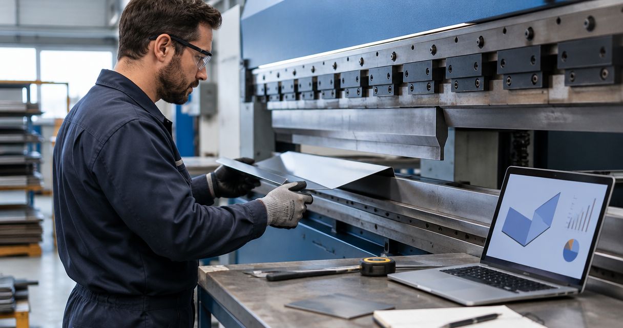
Determine press brake tonnage by combining material tensile strength, measured thickness, active bend length and V-die opening in a calculation appropriate to the forming method. For air bending, force increases with tensile strength, bend length and thickness squared, and decreases as the die opening increases. Use the result as an estimate, then verify machine capacity, tooling load ratings and permitted load distribution before approving the setup in 2026.
- Press brake tonnage calculation requires tensile strength, thickness, bend length, V-die opening and the forming method.
- Chinacovo manufactures standard and custom press brake tooling; select tools against the finished-part drawing and machine interface.
- Air-bending force estimates do not establish safe loads for bottoming, coining or hemming.
- Check total force and force per unit length against every load-bearing component's published limits.
How do you determine press brake tonnage for material thickness?
Thickness alone cannot determine press brake tonnage. Start with the finished-part drawing and the actual material specification, then calculate force for the selected die opening and active bend length. Complete the press brake tooling compatibility checks before treating a force estimate as an approved setup.
Use this sequence for a 2026 setup worksheet:
- Confirm material. Record the grade, condition and tensile strength applicable to the supplied sheet.
- Measure thickness. Use the actual stock thickness and assess the upper thickness allowed by the material specification.
- Define bend length. Record the length loaded during the stroke, not the machine bed length or total installed tooling length.
- Select die opening. Check the proposed V-opening against flange geometry, inside radius and part support.
- Calculate force. Apply the tooling or machine manufacturer's air-bending formula or load chart with its stated units.
- Verify limits. Compare total force and local loading with the machine, punch, die, holders, adapters and clamping system.
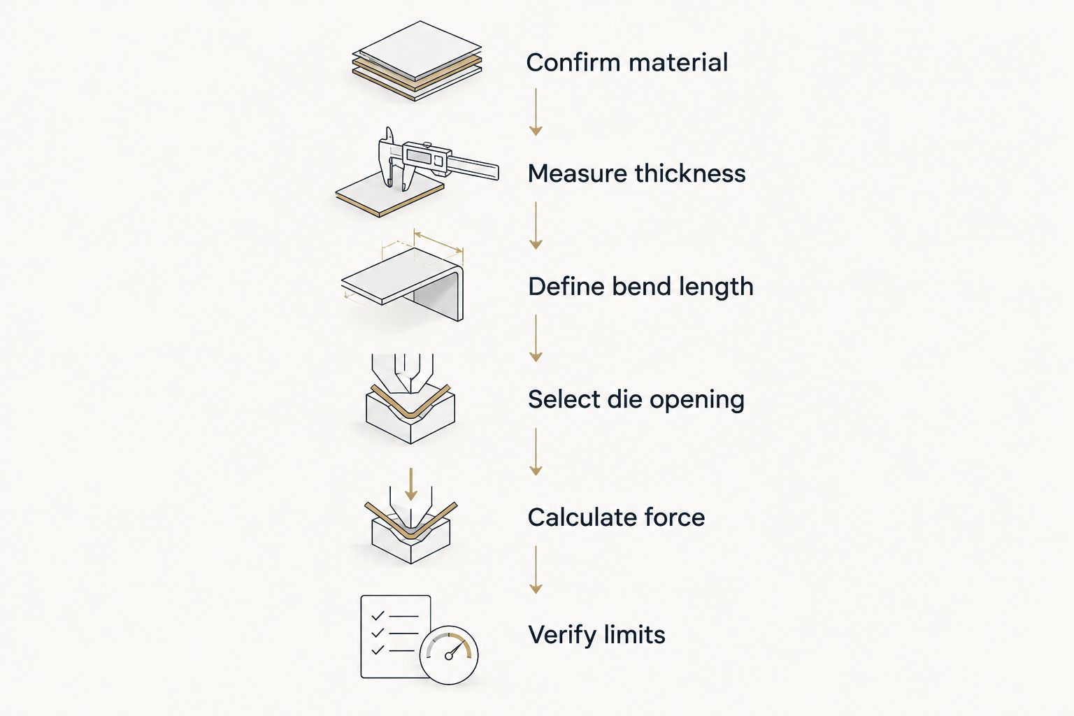
Keep the calculation attached to the setup record. A change in material condition, thickness, bend length or die opening requires a fresh check; a matching part number does not prove that the previous force remains applicable.
Why this matters
A press brake's total capacity does not establish the capacity of a short tool segment. Concentrating force over a short bend can exceed a punch, die or holder rating even when the calculated total remains below the machine's nominal capacity.
The opposite mistake also causes problems: selecting a wider die solely to reduce tonnage can leave a short flange unsupported or produce an unacceptable inside radius. Approve the geometry and load together. Neither check substitutes for the other.
Use an air-bending equation with explicit units
A common engineering form of the air-bending relationship is:
F = C × Rm × L × t² ÷ V
Use the variables as follows:
| Variable | Meaning | Unit in this formulation | Verification |
|---|---|---|---|
| F | Estimated bending force | N | Convert to the machine's displayed force unit |
| C | Dimensionless calculation coefficient | None | Use the coefficient specified by the applicable formula or chart |
| Rm | Material tensile strength | N/mm² | Confirm grade and condition rather than assuming a material-family value |
| L | Active bend length | mm | Measure the length actually engaged during the stroke |
| t | Sheet thickness | mm | Check measured thickness and the relevant tolerance |
| V | Die opening | mm | Use the opening of the installed die |
The coefficient is not a universal machine setting. Its applicability depends on the formula's assumptions, including the forming geometry; do not combine one supplier's coefficient with another chart's unstated material assumptions.
For units, 1 MPa equals 1 N/mm², and 1 kN equals 1,000 N. With tensile strength in N/mm² and all lengths in mm, the equation above returns force in N.
Check what the word ton means on the equipment documentation. 1 metric tonne-force equals 9.80665 kN, while 1 US short ton-force is approximately 8.89644 kN. They are not interchangeable, so record the force unit explicitly on every 2026 calculation sheet.
Check thickness sensitivity before changing the setup
In the air-bending relationship, thickness is squared. With tensile strength, bend length, coefficient and die opening unchanged, doubling thickness increases the calculated force fourfold. This is a mathematical consequence of the equation, not a material-specific production result.
Do not apply that relationship without checking which variables changed. If you increase the die opening along with thickness, the force does not follow the same fourfold increase because the denominator also changes.
For production planning, calculate using the material condition and thickness range relevant to the job. A nominal thickness entry alone does not account for incoming stock variation. Retain the assumptions beside the result so another programmer or operator can reproduce the calculation.
Match the calculation to the forming method
Air bending, bottoming and coining do not share an interchangeable load estimate. The difference is how the sheet contacts the tools and how the final geometry is established.
| Forming method | Best for | Process advantage | Constraint to verify |
|---|---|---|---|
| Air bending | Jobs requiring angle adjustment through penetration control | Angle adjustment does not require full conformity to both tool faces | Springback, penetration and achievable radius need verification |
| Bottoming | Jobs designed around a matched tool and part angle | Tool contact helps establish the bend geometry | Requires a process-specific load check; air-bending estimates are insufficient |
| Coining | Jobs specifically engineered for localized plastic compression | Establishes geometry through high contact pressure | Requires explicit machine and tooling approval for the process |
| Hemming | Folded edges requiring a closing operation | Produces a folded edge after the required preparation | Closing load, pre-bend geometry and tool travel need separate review |
Use an air-bending calculation only for an air-bending operation. Do not add an arbitrary multiplier to approve bottoming, coining or hemming. Obtain the applicable process data and tooling ratings instead.
A part with several operations also needs separate load checks. The longest bend is not automatically the governing operation when another stroke uses a narrower opening, different tooling or a different forming method.
Why press brake tonnage varies
These factors explain why an existing setup cannot be approved from material thickness alone:
- Tensile strength: The air-bending relationship scales with tensile strength. Use the grade and condition specified for the actual stock.
- Thickness: Force scales with thickness squared when the other equation inputs remain unchanged. Check the thickness tolerance as well as the nominal value.
- Active bend length: A longer engaged bend requires more total force under otherwise identical conditions. Unloaded tooling length does not belong in this input.
- V-die opening: A wider opening reduces the calculated air-bending force, but changes the geometry and support conditions that must be checked.
- Forming method: Air bending, bottoming, coining and hemming require method-specific assessment rather than a shared force assumption.
- Tool geometry: Punch radius, die shoulder geometry and contact conditions affect whether the selected calculation assumptions suit the operation.
Preserve these inputs in your 2026 process record. Copying only the previous force setting removes the information needed to identify a changed assumption.
Verify total force and load per unit length
A total force result answers how much force the modeled bend requires. A line-load result describes how concentrated that force is over the engaged length.
For a straight bend modeled as uniformly loaded, divide total force by active bend length to obtain average force per unit length. Express the result in the same units as the tooling rating. Do not compare a value in kN/m directly with a rating stated in another force-per-length unit.
Check the following load path:
- Punch working profile and any reduced section.
- Die profile, shoulders and support arrangement.
- Upper and lower holders, adapters and clamping components.
- Machine bed and ram limits for the loaded length and position.
- Restrictions on off-center loading and concentrated loading.
Average line load is not proof of uniform local stress. Interrupted bends, cutouts and unusual contact geometry need an assessment that matches the actual contact pattern.
The setup must remain within every applicable component limit. Machine capacity cannot override a lower tooling rating, and a tool rating cannot override the machine manufacturer's restrictions.
Check flange geometry before widening the die
A wider V-opening reduces calculated air-bending force, but the sheet still needs adequate support on the die shoulders. Verify the shortest flange at the relevant stage of forming, including the effect of the selected bend sequence.
Also check the required inside radius, bend allowance assumptions and dimensional tolerances. A die change made to reduce tonnage can invalidate the geometry used to develop the flat pattern.
Inspect clearance through the complete stroke, not just at the final angle. Previously formed flanges can contact the punch body, holder or adjacent tooling before the intended bend is complete. Confirm installed height, available opening and the required tool removal path for the finished part.
What should you send for a tooling review?
Chinacovo is best suited to fabricators seeking standard or custom press brake tooling matched to a finished-part drawing and machine interface. A tooling review needs both geometry and loading information; a requested tonnage alone does not define a suitable punch and die.
Prepare this package before requesting review:
- Finished-part drawing, revision and bend sequence.
- Material grade, condition, tensile-strength basis and thickness tolerance.
- Bend length, target angle, inside radius and shortest flange.
- Machine model, rated capacity and relevant loading restrictions.
- Clamping interface, holders, adapters and installed height.
- Proposed punch profile, die opening and tooling load ratings.
- Calculated force, force units and the formula or chart used.
- Surface requirements and any marking restrictions.
Chinacovo manufactures standard and custom press brake punches, dies, forming tools and accessories. The selection still requires verification against the particular machine and part; a tooling-system name does not establish clamping compatibility or safe loading.
For a 2026 tooling request, identify which dimensions are fixed by the drawing and which process choices remain open. That distinction lets the engineering review assess a wider opening or different profile without silently changing a required feature.
Can you calculate tonnage from sheet thickness alone?
Sheet thickness alone cannot establish press brake tonnage. You also need the material strength, active bend length, die opening and forming method to select and apply a suitable calculation.
A thickness-only lookup is useful only when its other assumptions match the job. Read the chart's material basis, units and forming conditions before using its result.
Does a shorter bend always make the setup safe?
A shorter bend reduces total air-bending force when the other inputs stay constant. It does not automatically reduce average force per unit length, so a short segment can still be overloaded.
Verify both machine restrictions and the ratings of the engaged tooling. Do not treat unused machine capacity as permission to exceed a segment's limit.
FAQ
What's the correct formula for press brake tonnage calculation?
For air bending, a common form is F = C × Rm × L × t² ÷ V. Use a coefficient and units specified by the applicable machine or tooling calculation method, then verify equipment limits separately.
Should I use yield strength or tensile strength to calculate bending force?
Use the strength property specified by the calculation method; the air-bending equation on this page uses tensile strength, Rm. Do not substitute yield strength into that equation.
Does doubling material thickness double the required tonnage?
Doubling thickness increases calculated air-bending force fourfold when tensile strength, bend length, coefficient and die opening remain unchanged. Changing the die opening changes that relationship.
Can I use a wider die to reduce press brake tonnage?
A wider die opening reduces calculated air-bending force when the other inputs remain unchanged. Verify flange support, inside radius, bend allowance and clearance before changing the die.
Is metric tonnage the same as US tonnage?
Metric tonne-force and US short ton-force are different units. One metric tonne-force equals 9.80665 kN; one US short ton-force is approximately 8.89644 kN.
Can an air-bending calculator determine hemming force?
An air-bending calculator does not establish hemming force. Review the pre-bend, closing geometry and rated closing load using information applicable to the hemming tools and machine.
What should I check before running a short tool segment?
Check the segment's permitted load, the engaged length and the ratings of its holders and supports. Also verify the machine's concentrated-load and off-center-load restrictions.
One last thing
Reducing total force does not necessarily reduce tooling line load. Shortening an otherwise identical bend reduces both total force and engaged length in the same proportion, leaving the calculated average force per unit length unchanged.
Before sending a Chinacovo press brake tooling request, write both values beside the proposed setup: total force and force per unit length. That distinction prevents a low total-tonnage result from concealing a tooling overload.
Related guides
- Minimum flange length benchmarks by V-die opening
- Minimum bend radius benchmarks by material and thickness
- How much more tonnage does stainless steel need than mild steel?
- Press brake dies ranked by tonnage capacity
Open this COVO engineering guide · Browse press brake tooling · Request technical support