COVO KNOWLEDGE
How to inspect press brake dies for wear before reordering
Published:
Updated:
Inspect press brake dies for wear before reordering. Check shoulders, V-opening, installed height and clamping fit, then document repair or replacement.
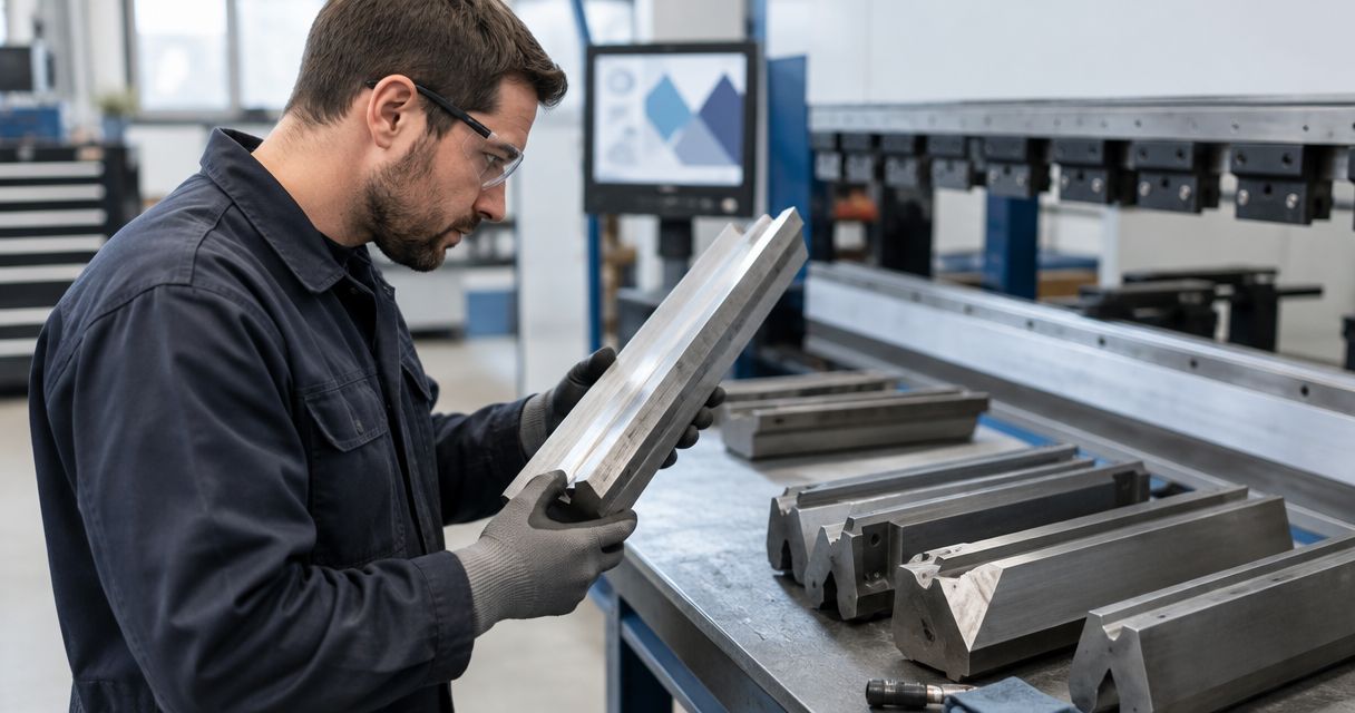
To inspect press brake dies for wear before reordering, clean and safely isolate the tooling, inspect the working shoulders and clamping interface, then compare measured geometry with the approved tool drawing. Separate wear from material pickup, seating errors and machine setup problems; reorder against verified specifications, not dimensions copied from a worn die.
- Inspect press brake dies for wear against approved drawings, not appearance alone.
- Quarantine dies with cracks, chipped working edges or damaged retention features pending qualified review.
- Chinacovo manufactures standard and custom press brake tooling; submit machine, material and finished-part specifications for review.
- Record V-opening, shoulder condition, installed height and segment alignment before choosing repair or replacement.
How do you inspect press brake dies for wear before reordering?
Follow the inspection sequence below, using the tool manufacturer's acceptance criteria and your site's machine-safety procedures. Your 2026 inspection record should identify the die, its position in the setup and the drawing revision used for comparison.
Replacement selection also requires a separate press brake tooling compatibility check. A matching V-opening does not establish matching clamping interface, installed height or load capacity.
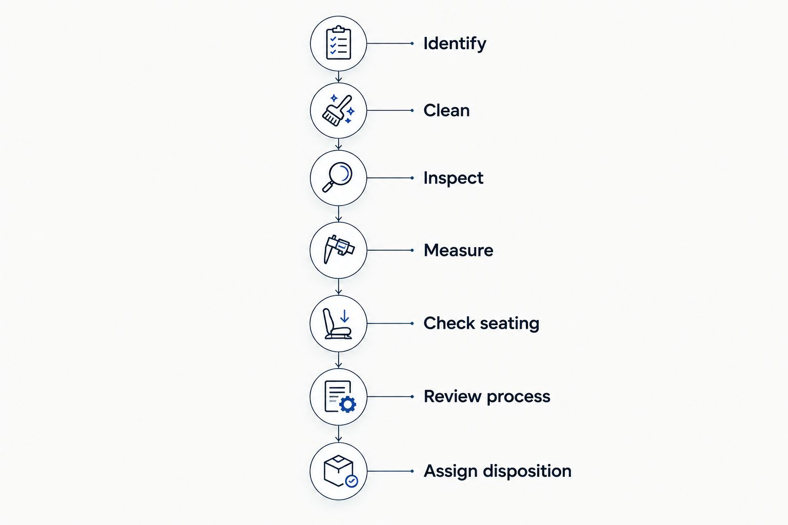
1. Isolate the machine and identify the die
Follow the press brake manufacturer's isolation procedure before entering the tooling area, removing guards or handling tooling. Use the prescribed lifting and support method when removing a die; do not inspect beneath an unsupported ram or suspended tool.
Record the tool identifier, profile, segment lengths, orientation and position along the bed. Photograph markings before cleaning removes temporary identification. Keep damaged or suspect tooling identified and separated from tooling released for production.
Find the approved drawing and any available inspection history. If identification is incomplete, treat the profile as unverified rather than assigning it the rating of a visually similar die.
2. Clean the working surfaces without changing their geometry
Remove loose debris, oil and transferred material using methods approved for the tool's material and surface treatment. Inspect the shoulders, V faces, segment ends, seating surfaces and locating features under suitable lighting.
Do not grind, stone or polish away a defect before documenting it. Abrasive work changes the surface you need to assess and can alter the working profile.
Distinguish material pickup from missing tool material. An attached deposit and a worn depression require different responses, even when both leave marks on the sheet. Photograph suspect areas before and after cleaning so the condition remains traceable.
3. Inspect shoulders, V faces and segment ends
Examine both working shoulders along the full used bend length. Look for flattened contact areas, uneven rounding, scoring, pitting, chipped edges and visible cracks. Compare heavily used areas with less-used areas, but use the approved drawing as the acceptance reference.
Inspect segment ends separately. Damage near a joint can interrupt sheet support even when the middle of each segment appears sound.
Mark each defect location on a sketch or inspection photograph. A visible crack requires removal from service pending qualified assessment, not a trial bend. Visual inspection also does not establish the absence of subsurface damage; obtain specialist examination when the condition warrants it.
4. Measure the profile against defined reference surfaces
Measure the V-opening at the reference location specified by the tool drawing. Rounded shoulders make an informal edge-to-edge measurement ambiguous, so record where the measurement was taken and which instrument was used.
Check shoulder geometry, overall height, seating geometry and straightness using suitable inspection equipment. Take readings along the used length and around suspect areas, rather than relying on a single measurement at one end.
Do not assign a universal wear allowance. Acceptance depends on the approved profile, manufacturer's limits and part requirements. A measurement is useful only when its reference surface and acceptance criterion are clear.
5. Check seating, clamping and installed height
Inspect the die's seating surfaces, locating features, holders and adapters for debris, damage or uneven contact. Check segment fit without forcing adjacent pieces together or improvising shims.
Distinguish overall tool height from installed height. The holder and adapter arrangement affects the working position; replacing the die alone does not correct an unsuitable or damaged mounting arrangement.
Record steps between adjoining segments and investigate their cause. A height mismatch can come from the tooling, the holder or contamination at the seat. Correct the identified cause before attributing the condition to shoulder wear.
6. Separate tooling wear from process variation
Review the jobs that produced the reported defect. Record material grade, measured thickness, bend length, punch radius, V-opening, bend method and the position of the bend on the machine.
Angle drift, surface marking and inconsistent flange geometry are symptoms, not proof of die wear. Check punch condition, sheet variation, alignment and machine compensation settings alongside the die inspection.
Only conduct a controlled verification bend after the tooling has passed the required safety and condition checks. Use approved setup procedures, compare the part with its drawing, and document settings. Do not use repeated depth changes to conceal an unresolved tooling defect.
7. Assign a documented disposition
Close the inspection with an explicit decision: release, specialist repair review or replacement review. Identify who authorized the decision and which drawing, measurement record and condition photographs support it.
For your 2026 tooling register, keep the inspection date separate from any claimed service-life estimate. Calendar age alone does not establish that the profile remains acceptable.
If the die requires replacement, preserve its identification and inspection evidence. Send the nominal specification with the measured condition; otherwise, a worn opening or altered shoulder can become an unintended feature of the replacement request.
Why this matters
Press brake die inspection has two separate objectives: establish whether the existing tool is acceptable, and define what the replacement must do. Combining those decisions encourages copying an existing setup without checking whether it still matches the finished-part requirements.
Your 2026 replacement specification should connect the tool profile to the required inside radius, flange geometry, material and bend length. The worn die is evidence of operating conditions, not the master specification.
What should each inspection finding trigger?
Use this table to organize the engineering review, not as permission to keep damaged tooling in service. Each route has a useful application and a limitation.
| Finding or route | Best for | Supporting evidence | Limitation or next check |
|---|---|---|---|
| Clean and reassess | Deposits obscuring the working surface | Before-and-after photographs and profile checks | Cleaning does not restore missing material or prove structural integrity |
| Release after verification | Tooling meeting documented acceptance criteria | Acceptable geometry, seating condition and required process checks | Release applies to the verified use, not every material or load |
| Specialist repair review | Assessing whether an altered profile can be restored | Original drawing, damage map and material information | Repair feasibility and resulting dimensions require approval |
| Replacement review | Damage or dimensions outside approved limits | Inspection record and nominal replacement specification | A new die does not correct holder or machine faults |
| Custom tooling review | Finished-part geometry requiring a different profile | Part drawing, machine interface and process requirements | Requires engineering verification rather than copying the old tool |
Do not infer a restored load rating from appearance after repair. Obtain the repair provider's documented limits and verify how any dimensional change affects the complete setup.
Why press brake die wear varies
The inspection scope should reflect how the die was used. Record these factors in the 2026 inspection sheet rather than assigning every die the same replacement interval:
- Material grade and thickness: Identify the actual stock processed. Both belong in the load calculation and tooling selection review.
- Bend length and load distribution: Record the engaged length and its location. A short working zone requires assessment against the tool's applicable loading limits.
- Bend method: Identify air bending, bottoming or another forming operation. Do not transfer acceptance or load assumptions between methods without verification.
- Surface condition: Record scale, debris, pickup and sheet-surface requirements. Distinguish cleaning needs from permanent changes to the die surface.
- Profile and part geometry: Check the selected opening, shoulder geometry, flange support and clearance against the finished-part drawing.
- Mounting condition: Inspect seating, alignment and segment fit. A sound working profile does not compensate for a damaged or incorrectly assembled interface.
For replacement planning, distinguish measured condition from general lifespan guidance in how long press brake dies last before replacement. Set the inspection interval through your maintenance and quality procedures, using the tool's condition and operating history.
What should you send for a replacement tooling review?
Send a specification package that allows the reviewer to distinguish nominal geometry from damage. Include the following:
- Finished-part drawing with revision, bend angles, inside radius, flange geometry and surface requirements.
- Material grade, thickness and required bend length.
- Machine model, clamping interface, holder and adapter details.
- Existing punch and die drawings, installed height and segment arrangement.
- Applicable machine and tooling load limits, including the basis for the engaged length.
- Inspection measurements, defect locations and photographs with a scale reference.
- Required disposition: like-for-like replacement, repair assessment or revised forming geometry.
Chinacovo press brake tooling is best suited to fabricators seeking standard or custom tooling reviewed against a finished-part drawing and machine interface. Chinacovo manufactures punches, dies, forming tools and accessories; that scope does not establish that a particular profile fits your setup.
For a 2026 reorder, confirm the proposed nominal geometry before approval. Review clamping, installed height, clearance and loads together, especially when replacing only part of a sectional set.
Prepare your tooling review
Collect the part drawing, machine interface, material specifications and inspection record before requesting review.
Can a polished die shoulder still be serviceable?
A polished shoulder is not, by itself, a rejection criterion. Compare the cleaned profile and surface condition with documented acceptance limits; a shiny contact band does not establish either acceptable geometry or excessive wear.
Should you replace one damaged segment or the complete set?
Replace only the affected segment when engineering review confirms that the remaining segments are acceptable and the replacement matches the required profile and installed height. Review the complete set when those conditions cannot be established; matching segment length alone is insufficient.
FAQ
What's the first step when inspecting press brake dies for wear?
Safely isolate the machine and identify the die before cleaning or measurement. Follow the machine manufacturer's procedures and use the prescribed handling equipment.
How much V-opening wear is acceptable?
The acceptable V-opening deviation comes from the approved tool drawing and manufacturer's criteria, not a universal allowance. Record the measurement location because shoulder rounding affects how an opening is measured.
Does a changing bend angle prove the die is worn?
A changing bend angle does not prove die wear. Check material thickness, punch condition, seating, alignment and process settings alongside measured die geometry.
Can I remove a chip by grinding the die myself?
Do not grind out a chip without an approved repair procedure. Material removal changes the profile and can affect installed height, surface condition and the setup's approved limits.
Can a replacement die use the old die's measured dimensions?
Use the approved nominal specification rather than copying worn dimensions. Include measurements of the old die as inspection evidence, clearly separated from the replacement requirements.
What does Chinacovo need for a custom press brake die review?
Provide the finished-part drawing, machine interface, material grade, thickness and required geometry for a Chinacovo custom tooling review. Add bend length, installed height, existing tooling details and the inspection findings.
One last thing
Inspect and photograph the die's underside before closing the report. A damaged seat or trapped contamination can change the working position even when the shoulders attract most of the attention.
Keep nominal dimensions and measured dimensions in separate fields. That distinction prevents an inspection report from becoming an incorrect replacement drawing.
Related guides
- Check tooling interchange between AMADA and TRUMPF
- Review segmented press brake dies for box forming
- Check minimum flange length by V-die opening
Open this COVO engineering guide · Browse press brake tooling · Request technical support