COVO KNOWLEDGE
Can worn press brake punches be reground instead of replaced?
Published:
Updated:
Regrind press brake punches only after verifying damage, geometry and load limits. Check tip radius, installed height and sectional fit before approving reuse.
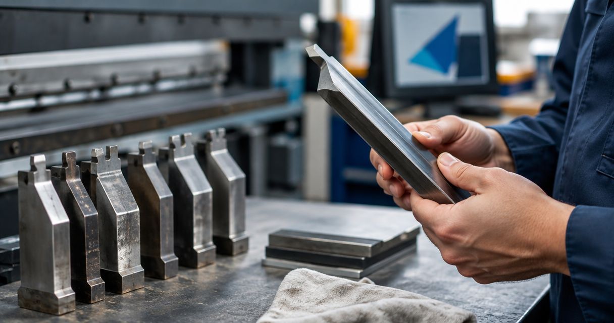
Yes, you can regrind press brake punches when an engineering assessment confirms that material removal will restore the working profile without compromising the tool’s geometry, hardened working region or load capacity. Regrinding also changes the dimensions used to set up the press brake, so the restored punch needs inspection and revised tooling data before production. Replace the punch when damage or the required material removal prevents a verified, serviceable profile.
- Regrind press brake punches only after verifying damage, remaining geometry, hardness requirements and permitted material removal.
- A restored punch needs measured installed height, tip radius and sectional alignment before production release.
- Replace punches when cracks, deformation or insufficient remaining material prevent an approved restoration.
- Chinacovo manufactures custom press brake tooling; replacement selection starts with the finished-part drawing and machine interface.
Can worn press brake punches be reground instead of replaced?
Regrinding is a conditional repair, not an automatic alternative to replacement. The decision depends on what caused the wear, how much material restoration requires and whether the resulting tool remains suitable for the intended bends.
Check the mounting arrangement separately from the working profile. A usable tip does not compensate for damaged seating surfaces or retention features; the tooling compatibility verification guide covers the interface checks that belong in that assessment.
| Decision | Best for | Advantage | Limitation |
|---|---|---|---|
| Regrind after engineering approval | Localized working-profile wear with sufficient serviceable material remaining | Retains an existing tool when restoration is technically acceptable | Changes dimensions and requires inspection, setup revision and process validation |
| Replace with a verified equivalent | Damage or material loss that prevents approved restoration | Establishes a replacement against a defined drawing and specification | Still requires interface, clearance and bending-process verification |
| Replace with a revised custom profile | Parts whose geometry no longer suits the existing punch | Allows the replacement geometry to address the actual part requirement | Requires a fresh engineering review rather than a like-for-like order |
Do not choose between these routes from photographs alone. Images document visible damage, but they do not establish material condition, hidden defects or the permissible finished dimensions.
Why this matters
A punch can look usable while its working profile no longer matches the tooling definition in the bend program. Conversely, visible wear does not by itself establish that the punch must be scrapped. The decision requires measurement and an acceptance basis.
For your 2026 maintenance records, separate the tool’s identity from its current geometry. Keep the original drawing, inspection findings and restored dimensions together so operators do not load the original tool definition against a modified punch.
The consequence is not limited to bend angle. Changes to tip radius, installed height or profile clearance affect how the punch interacts with the sheet, die and previously formed flanges.
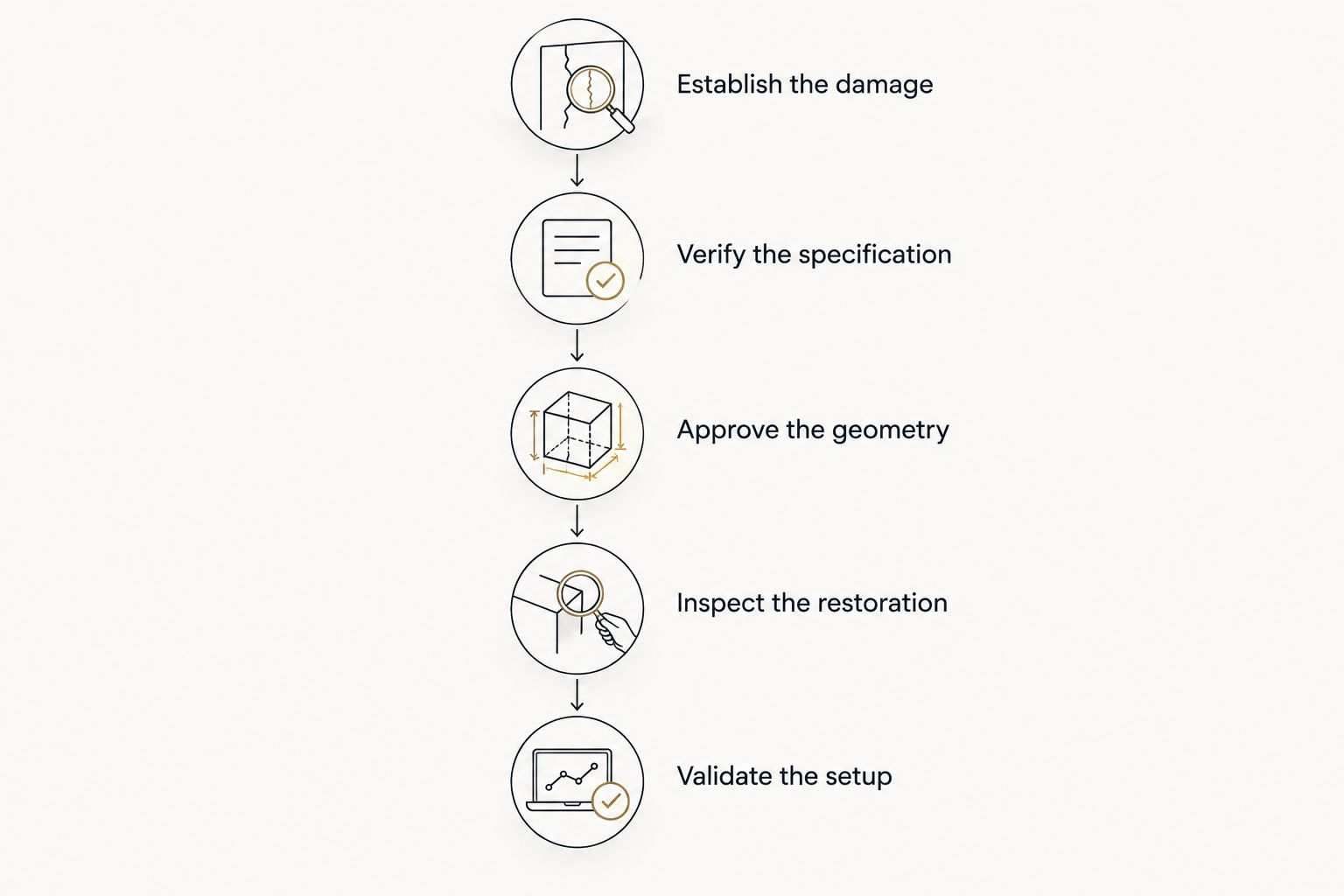
How to assess a punch before approving regrinding
Establish the damage
Remove the punch from production and identify the affected working surfaces. Record wear, chipping, scoring, indentation, corrosion and any suspected cracking without treating them as equivalent defects.
Inspect the tang, seating faces and retention features as well as the nose. Quarantine a punch with suspected cracks or deformation pending qualified assessment. Do not use a trial bend as a structural inspection.
Verify the specification
Identify the punch drawing, material specification, heat-treatment information, original profile and previous repair history. Where those records are incomplete, establish an engineering acceptance basis before authorizing material removal.
Check the actual clamping interface rather than relying on a tooling-system name. Confirm the machine, holder, retention arrangement and installed height associated with the tool’s intended use.
Approve the geometry
Define the proposed finished profile before grinding begins. The review should identify the required tip radius, included angle, tool height and any clearance-critical features.
Compare that geometry with the finished-part drawing, material grade, thickness, bend length and flange geometry. A profile that is straightforward to grind is not necessarily suitable for the part.
Inspect the restoration
Require inspection against the approved restoration drawing or acceptance specification. Check the working profile along the usable bend length rather than measuring only an accessible end.
For sectional punches, identify every segment included in the inspection. Record which segments belong together and confirm their restored relationship before returning them to a shared setup.
Validate the setup
Update the tooling definition using the measured restored dimensions. Follow the machine manufacturer’s setup and safety procedure, verify clearances and conduct controlled bending trials against the part requirements.
Release the tool only after both tooling inspection and part validation are complete. A bend-angle correction alone does not establish acceptable tool condition or load capacity.
Tip-profile regrinding: verify radius and working angle
Tip wear requires more than making the nose appear smooth. Restoration must produce the approved radius and working angle while retaining a serviceable tool section.
A changed punch radius can affect bending behavior and the resulting inside radius. In air bending, the die opening and material also influence the formed radius; do not assume that restoring the punch radius alone restores the complete process.
Check surface condition after restoration as well. Grinding marks, burrs or an unacceptable working finish can affect sheet contact and surface quality.
Your 2026 restoration drawing should identify the required finished geometry and inspection criteria. Do not substitute a general instruction such as “sharpen the punch” for a dimensioned requirement.
Sectional punch regrinding: verify the matched set
Sectional tooling needs a set-level decision. Regrinding one segment changes its relationship to neighboring segments unless the restoration plan accounts for the assembled working profile.
Check these features across the intended bend length:
- Working height: confirm the restored segments form the required common working line.
- Tip profile: verify radius and angle across segment boundaries.
- Seating condition: distinguish dimensional differences from incomplete seating or damaged contact faces.
- Segment identification: keep inspection records tied to the physical pieces.
- End clearance: confirm the segment arrangement still permits the intended box or flange geometry.
Do not correct mismatched segment height with improvised packing. Use only arrangements approved for the machine, holder and tooling system.
Replacement: define what the new punch must preserve
Replacement is appropriate when the assessment cannot establish an acceptable restored tool. Examples include structural damage, insufficient remaining material or a required profile that cannot be recovered within the approved geometry.
A replacement order still needs technical definition. Matching the visible outline does not establish the correct tang, retention features, installed height or allowable loading.
Chinacovo press brake tooling is best for fabricators who need custom punch geometry defined from finished-part drawings and machine-interface requirements. The limitation is that a new profile still needs review against your machine, material and bending sequence; a tooling description is not setup approval.
For a Chinacovo press brake tooling review, provide the finished-part drawing, machine interface, material grade, thickness and required geometry. Distinguish dimensions that must match the existing setup from dimensions that can change.
Review the replacement tooling requirements
Prepare the part drawing, machine interface, material grade, thickness and required geometry.
Why regrinding suitability varies
The restoration decision changes with the tool’s condition and intended application. Use these factors to structure the review rather than applying a universal wear allowance:
- Damage mechanism: ordinary working-profile wear needs a different assessment from cracking, deformation or overload damage.
- Material condition: tool steel, heat treatment and any surface treatment determine what restoration requires verification.
- Material removal: the proposed cut must leave an acceptable working section and finished geometry.
- Part requirements: radius, flange geometry, bend length and surface requirements determine whether the restored profile is useful.
- Machine arrangement: clamping interface, installed height, stroke and clearance constrain the restored setup.
- Tooling configuration: sectional sets and mixed-height arrangements require checks beyond a single punch measurement.
For a 2026 repair request, document these factors before choosing a restoration route. The useful question is not simply whether the punch can be ground, but whether the proposed finished punch can be approved for its assigned work.
What information should you send for a tooling review?
Send enough information to connect the damaged tool to the part and machine. A photograph without a drawing or setup context leaves critical engineering questions unanswered.
Include the following in the review package:
- Finished-part drawing with bend angles, inside radii and flange dimensions.
- Material grade, thickness and relevant surface requirements.
- Machine and holder identification, plus clamping-interface details.
- Punch drawing or measured profile, including installed height and tip radius.
- Photographs showing the complete tool, working surface, mounting features and damaged area.
- Intended bend length, die arrangement and operating load information.
- Previous regrinding records and the tool definition currently used by the machine.
Keep your 2026 inspection report separate from the original manufacturing drawing, but cross-reference both. This preserves the distinction between the tool as supplied and the tool as restored.
Ask the reviewer to state the acceptance criteria, required inspections and restrictions on reuse. Do not treat an unqualified instruction to remove the visible wear as a restoration specification.
Does regrinding change the punch load rating?
Do not carry the original load rating forward without verification. Material removal changes geometry, and damage can affect the condition on which the original rating depended.
The manufacturer or qualified tooling engineer must assess the restored configuration. Check the permitted loading for the actual tool and bend length, as well as the limits of the holder, die and machine.
Can you reuse the original bend program after regrinding?
Do not reuse the original tooling definition unchanged when the measured geometry has changed. Revise the relevant tool dimensions and verify the setup before running production parts.
For a 2026 production release, record the approved program and restored-tool identification together. Confirm bend angle, flange dimensions, surface condition and sequence clearance against the finished-part drawing.
FAQ
Can all worn press brake punches be reground?
No. Regrinding requires an assessment showing that the restored geometry and material condition remain acceptable for the intended work. Cracks, deformation or insufficient remaining material can rule out restoration.
Is regrinding a press brake punch better than replacing it?
Regrinding is appropriate only when it produces an approved, serviceable tool. Replacement is the appropriate route when restoration cannot meet the required geometry, condition or application requirements.
How much material can be removed from a press brake punch?
The permitted material removal must be established for the specific punch. Use its drawing, material and heat-treatment information, condition and required finished geometry rather than a general allowance.
Can I regrind only one segment of a sectional punch?
A single segment requires assessment against the complete working set. Verify restored height, tip profile and seating so the assembled segments meet the required working geometry.
Does regrinding change the inside bend radius?
Regrinding can change bending behavior if it changes the punch tip radius or profile. In air bending, the die opening and material also influence the formed radius, so validate the complete setup.
Can a cracked press brake punch be ground smooth and reused?
Grinding a visible crack smooth does not establish that the punch is safe to reuse. Quarantine the tool and obtain qualified assessment rather than returning it to service on appearance alone.
Does Chinacovo need the finished-part drawing for replacement tooling?
Chinacovo custom press brake tooling should be defined from the finished-part drawing and machine interface. Include material grade, thickness, bend length, radius and flange geometry so the replacement addresses the actual application.
One last thing
Inspect the setup that produced the wear before approving the repaired tool. Damaged seating surfaces, an unsuitable load arrangement or interference with a formed flange remain process problems even after the punch profile has been restored.
Keep the original tool identification attached to its repair history. The practical release document is the approved current geometry—not the original catalog description and not a photograph of a clean working surface.
Related guides
- Press brake punches ranked by radius tolerance
- Can you mix press brake punches and dies from different brands?
- Minimum bend radius benchmarks by material and thickness
- Custom press brake tooling for OEM fabricators
Open this COVO engineering guide · Browse press brake tooling · Request technical support