COVO KNOWLEDGE
Can standard press brake dies bend aluminum without marking it?
Published:
Updated:
bend aluminum without marking press brake dies: Check die shoulders, protective barriers, radius and material, then prove the finish on a sample.
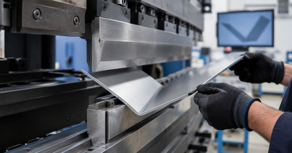
Yes—standard press brake dies can bend aluminum without unacceptable visible marking, but a bare steel V-die does not guarantee a mark-free surface. Die condition, shoulder geometry, aluminum grade and temper, surface finish, and protective barriers determine the result; qualify the complete setup on representative material before releasing production.
- Standard press brake dies can bend aluminum without unacceptable marking; qualify the finish on representative material.
- Clean die shoulders prevent debris scratches, but polishing alone does not eliminate pressure marks.
- Protective film and purpose-made die barriers require separate checks for bend angle, radius and surface transfer.
- Chinacovo manufactures standard and custom press brake tooling; selection starts with the finished-part drawing and machine interface.
Can standard press brake dies bend aluminum without marking it?
Standard dies are acceptable only when the resulting contact marks meet the finished-part requirement. A functional bracket and a visible architectural panel do not necessarily have the same acceptance criteria. Define the permitted appearance before deciding whether the existing tools are suitable.
During air bending, the sheet bears against the die shoulders and moves across those contact surfaces. Clean steel tooling can still leave witness lines because removing abrasive contamination does not remove contact pressure or sliding contact.
Start with a documented inspection of press brake dies for wear. Check the working surfaces rather than assuming a die is suitable because its V-opening matches the setup sheet.
| Setup option | Best for | Main advantage | Limitation to verify |
|---|---|---|---|
| Clean, undamaged standard steel V-die | Parts whose finish specification permits qualified contact lines | Retains the existing tooling arrangement | Direct steel contact can leave witness lines |
| Standard die with a purpose-made protective barrier | Surface-sensitive parts that fit the validated protected setup | Separates the aluminum from the steel shoulders | Barrier wear and compression affect repeatability |
| Die with purpose-made nonmetallic contact elements | Jobs requiring a different contact surface | Changes the sheet-to-tool contact interface | Load rating, wear and geometry require verification |
| Roller-style or application-specific die | Parts requiring a different contact mechanism | Changes how the sheet moves over the supports | Flange support, machine fit and tooling limits still apply |
These are alternative setups to evaluate, not interchangeable fixes. Changing the contact arrangement requires renewed dimensional and surface inspection.
Why this matters
A bend can meet its angle requirement and still fail visual inspection. Conversely, a faint contact line can be acceptable when it falls outside the designated cosmetic surface or meets an approved reference sample.
For a 2026 production release, document the actual acceptance condition: finished surface, viewing conditions, permitted witness lines and any later finishing operations. “No marking” is not a usable shop-floor instruction unless operators and inspectors recognize the same pass condition.
Keep surface acceptance separate from structural acceptance. A clean-looking bend does not establish that the selected radius is suitable for the aluminum grade, temper and grain direction.
Standard steel dies: qualify the contact surfaces first
Best for: aluminum parts whose surface requirements can be met with the existing steel contact geometry.
Inspect both die shoulders along the full bend length. Look for embedded particles, raised damage, aluminum pickup and changes in surface condition at segment joints. Inspect the punch contact area as well; a mark on the part does not automatically originate at the die.
Clean tooling using the tool manufacturer's approved procedure. Do not grind or reshape a shoulder informally to remove a visible line. Altering the working profile changes the geometry that supports the sheet and requires engineering review.
A polished shoulder removes one source of abrasion, but it does not eliminate load concentration. If a clean, undamaged die produces a repeatable witness line, investigate the contact arrangement rather than repeating the cleaning operation.
The advantage of retaining standard tooling is that the machine interface and setup arrangement remain familiar. The limitation is direct contact between the aluminum and the tool: the finish must prove acceptable under the actual forming conditions.
Protected standard dies: verify the barrier as tooling
Best for: surface-sensitive parts where a purpose-made barrier can separate the sheet from the die without compromising the required geometry.
A protective barrier is part of the forming stack, not merely packaging. Its thickness, compressibility, position and condition affect the relationship between ram movement and the finished bend. Establish the setup with the barrier installed.
Check these conditions before accepting the protected setup:
- Coverage: the barrier covers every intended die-contact area throughout the bend.
- Condition: no embedded chips, tears, folds or damaged areas contact the workpiece.
- Retention: the barrier remains positioned according to its supplier's instructions.
- Geometry: the protected arrangement achieves the specified angle, radius and flange geometry.
- Surface transfer: the barrier leaves no unacceptable texture, residue or impression.
Factory-applied sheet film is a separate variable. Do not assume that a film intended for handling protection is approved for forming. Verify its suitability with the material or film supplier, then inspect the surface underneath it on a representative sample.
Record the barrier specification in the 2026 setup documentation. A replacement material that looks similar is not automatically an equivalent forming component.
Alternative contact tooling: review the whole assembly
Best for: applications where standard die shoulders, with or without a barrier, cannot meet the qualified finish requirement.
Purpose-made nonmetallic contact elements and roller-style dies change the contact interface. That makes them candidates for evaluation, not a universal guarantee against marking. Their suitability depends on the specific tool design, material and part geometry.
Verify the assembly's rated load, usable bend length, opening, installed height and retention arrangement. Check the required flange support and available machine travel before treating an alternative die as a drop-in replacement.
The benefit is a different method of supporting the aluminum during forming. The trade-off is another tooling arrangement to qualify and maintain. Worn inserts, contaminated contact elements or an unsuitable profile can defeat the surface-protection objective.
Select the contact method against the drawing, not against a general “non-marking” label. Keep the tool supplier's operating limits with the approved setup instructions.
Why aluminum marking varies
The visible result depends on interacting material and tooling conditions. Record these factors before comparing samples; otherwise, a change attributed to the die can actually come from the sheet or setup.
- Material grade and temper: these influence forming behavior and the bend geometry that the material can tolerate.
- Surface condition: mill finish, brushed surfaces, coatings and protective films require different appearance checks.
- Tool condition: debris, pickup, damaged shoulders and segment discontinuities can create localized marks.
- Contact geometry: V-opening, shoulder radius and punch profile affect support, contact and the resulting bend.
- Part geometry: bend length, flange geometry and adjacent features determine whether the part remains properly supported and clears the tools.
- Forming method: air bending, bottoming and coining use different contact and loading conditions; approval of one method does not qualify another.
For radius selection, use the actual material specification and the part drawing. The minimum bend radius guide provides related context, but the production decision still requires the specified alloy, temper, thickness and grain direction.
Do not widen the V-opening solely to reduce visible contact without checking the consequences. The revised setup must still produce the required radius, support the flange and remain within machine and tooling limits.
How do you qualify a setup before production?
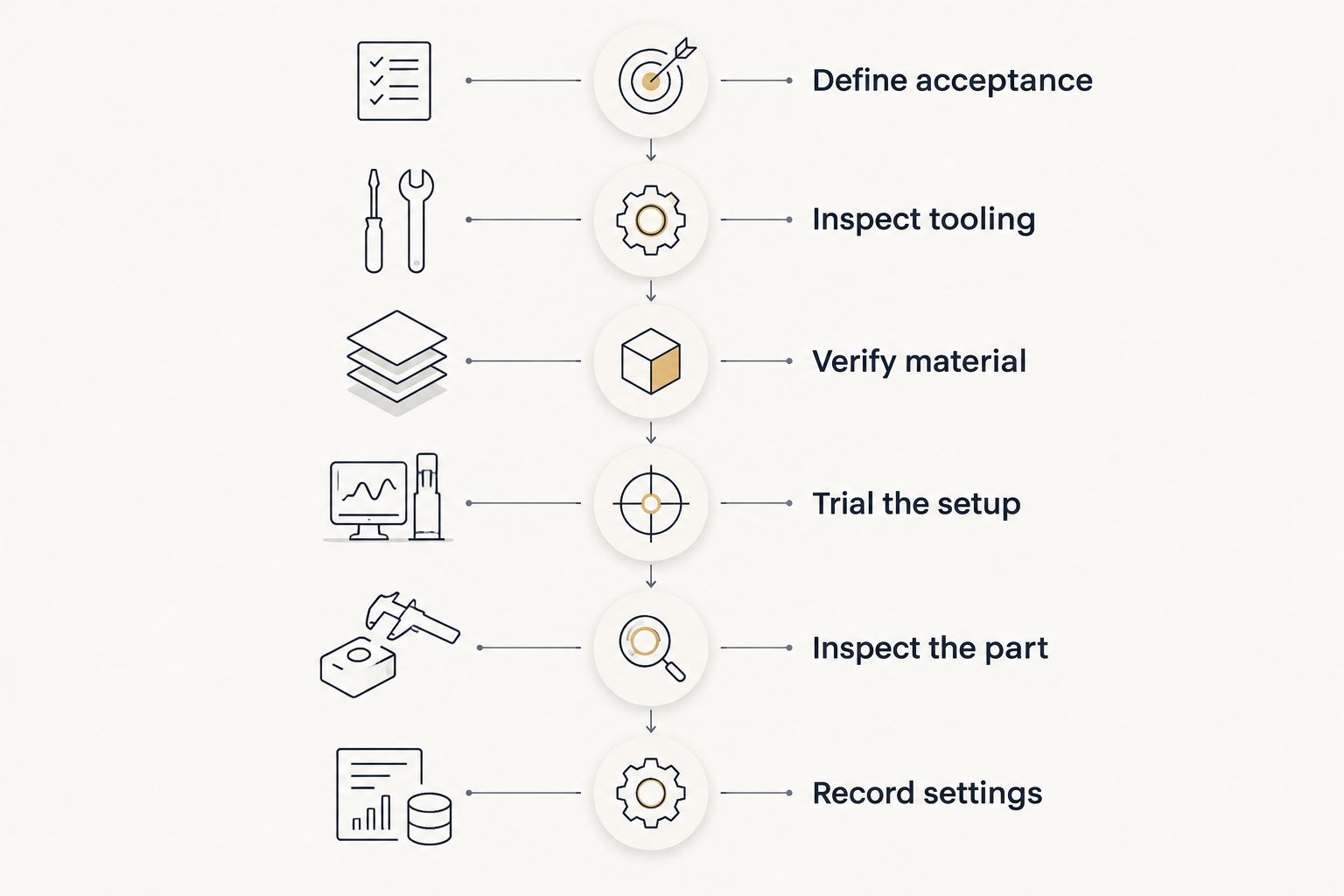
Use a controlled trial that separates surface protection from dimensional acceptance. Follow the machine and tooling suppliers' operating instructions, and keep hands outside the working area during machine movement.
- Define acceptance. Identify the cosmetic face, permitted contact lines, inspection lighting and required final finish. Use an approved sample when available.
- Inspect tooling. Check the punch, die shoulders, segment joints, clamping interface and seating surfaces. Confirm the selected assembly's load limits.
- Verify material. Confirm grade, temper, measured thickness, grain direction and surface condition against the job requirements.
- Trial the setup. Use representative material with the intended tooling, barrier, bend length and forming method. Check approach, clearance and support before forming.
- Inspect the part. Measure angle, radius and flange geometry, then assess the designated surfaces. Inspect beneath removable protection according to the agreed procedure.
- Record settings. Retain the approved tooling arrangement, protection specification, inspection result and setup instructions for repeat production.
For repeat work in 2026, retain an approved surface reference alongside the dimensional record. A photograph helps locate a mark, but it does not replace an agreed physical reference when lighting or texture changes the appearance.
Change one setup variable at a time during troubleshooting. If you change the die opening, barrier and material condition together, the trial does not isolate which change affected the result.
What should you send for a tooling review?
Send the finished-part drawing first, followed by the machine and material information needed to evaluate it. A photograph of a marked panel identifies the symptom; it does not establish the correct working profile.
Include:
- Material grade, temper, thickness and grain direction relative to the bend.
- Required angle, inside radius, bend length and flange geometry.
- Cosmetic-face identification and the surface acceptance requirement.
- Existing punch and die drawings, including the V-opening and shoulder profile.
- Machine model, clamping interface, retention arrangement and installed height.
- Available travel, clearance constraints and the intended bend sequence.
- Current forming method, protective material and photographs locating the marks.
Chinacovo is best suited to fabricators seeking standard or custom press brake tooling matched to finished-part and machine requirements. Chinacovo manufactures punches, dies and forming tools; the selection still requires verification of interface, geometry and loads. A custom profile alone does not establish an acceptable surface finish.
For a 2026 tooling review, identify the drawing revision and distinguish measured setup dimensions from nominal catalog dimensions. Keep unresolved geometry or finish requirements visible in the request rather than leaving the supplier to infer them.
Review the tooling requirements
Prepare the finished-part drawing, machine interface, material specification and surface acceptance criteria.
Will polishing a standard die eliminate aluminum marks?
Polishing a standard die does not guarantee elimination of aluminum marks. It can address surface roughness, but pressure-related witness lines require evaluation of the contact geometry and forming conditions.
Use an approved maintenance process. If polishing changes the shoulder profile, the die requires dimensional and application review before reuse.
Can you use the existing bend program with a protective barrier?
An existing bend program is not automatically qualified after adding a protective barrier. Verify the finished angle, radius and flange dimensions with the barrier installed, and follow the machine's approved setup procedure.
Retain the original program identification and document the protected setup separately. Do not treat an unrecorded operator correction as a controlled production standard.
FAQ
Can standard V-dies bend aluminum without leaving visible lines?
Standard V-dies can produce an acceptable aluminum finish, but visible-line acceptance must be demonstrated on representative material. Clean shoulders, suitable geometry and any protective barrier must be evaluated as a complete setup.
What's the best way to protect a cosmetic aluminum face during bending?
The best method is the contact arrangement that passes both surface and dimensional inspection for the specified part. Compare clean standard tooling, a purpose-made barrier and alternative contact tooling against the same acceptance criteria.
Can chips trapped under protective film still scratch aluminum?
Trapped chips can mark aluminum even when protective film is present. Inspect the sheet, tooling and barrier surfaces before forming rather than treating film as a substitute for cleanliness.
Is a wider V-opening always better for avoiding marks?
A wider V-opening is not automatically better because it changes the forming geometry and flange-support requirement. Verify the resulting radius, required load and minimum supported flange before approving the change.
Does an acceptable surface mean the aluminum bend is structurally sound?
An acceptable surface does not establish structural suitability. Check the specified grade, temper, grain direction and bend radius, and inspect for cracking according to the part requirements.
What information does Chinacovo need for an aluminum tooling review?
A Chinacovo press brake tooling review should start with the finished-part drawing, material grade and thickness, machine interface and required geometry. Include the cosmetic-face requirement, existing tool drawings and photographs identifying the marking locations.
One last thing
Inspect the face that contacts the punch as deliberately as the face that contacts the die. Treating every aluminum mark as a die problem can leave the actual contact source unchanged.
For the final 2026 release check, map each unacceptable mark to a specific contact location. That gives the next tooling decision a defined problem to solve: contamination, damaged tooling, pressure contact, sliding contact or part interference.
Related guides
- Press brake tooling for electrical enclosures
- Verify press brake tooling compatibility before ordering
- Sheet metal hemming tools for aluminum panels
Open this COVO engineering guide · Browse press brake tooling · Request technical support