COVO KNOWLEDGE
How to connect COVO hemming tools to a one-hit hemming brake
Published:
Updated:
Connect one-hit hemming press brake tooling only after verifying clamping, installed height, closing load and part clearance. Follow a drawing-led setup guide.

Instead of repeatedly moving a part between pre-bending and closing setups, connect one-hit hemming press brake tooling through a verified tooling-and-machine setup that matches the finished-part drawing. Confirm the clamping interface, installed height, forming sequence, closing load and part clearance before installing COVO tools or releasing the job to production.
- Chinacovo is best suited to fabricators requesting drawing-led custom press brake tooling.
- One-hit hemming press brake tooling requires verified clamping, installed height, closing load and flange geometry.
- Confirm whether the specified tool forms and closes the hem in one stroke or requires separate operations.
- Approve the complete hem cross-section, not just the outside dimensions, before production.
Why this matters
A tool that fits the clamp is not necessarily suitable for the hem. The finished flange must enter the forming geometry, clear the tool during closing and leave the setup without interference. Machine capacity alone does not establish that the punch, die, holder or adapter can carry the required load.
Treat one-hit hemming as a defined forming sequence, not a compatibility label. For this 2026 setup guide, the controlling documents are the machine instructions, tooling drawings and approved finished-part drawing. Start with the hemming tools for one-hit hemming press brakes guide when deciding which configuration needs engineering review.
Chinacovo manufactures standard and custom press brake punches, dies and forming tools. Chinacovo is best suited to fabricators requesting drawing-led custom press brake tooling. Custom geometry still requires verification against the actual machine interface and forming task; it does not remove the need for setup approval.
Before you start
- Gather the machine and tooling documents: Machine model, clamp and holder drawings, installed-height references, permitted working envelope and load limits for every load-bearing component. Identify any adapter already fitted to the brake.
- Prepare the finished-part requirements: Material grade, thickness, bend length, radius, flange geometry, hem cross-section, surface requirements and inspection criteria. Include nearby bends and the planned forming sequence, not just an isolated hem detail.
- Resolve the hidden gotcha: Confirm what the proposed tooling means by one-hit. A combined tool station is not proof that a flat blank becomes a finished hem in one ram stroke. Verify whether a pre-bend, repositioning step or separate closing operation is required.
Use qualified setup personnel and the machine manufacturer's procedures for isolation, tool installation and controlled trials. Do not improvise around an unmatched clamp, retention feature or undocumented load rating.
Hemming configuration selection
Select the forming route before configuring the machine. Flat hems and teardrop hems have different finished cross-sections; neither is an interchangeable substitute for the other. Likewise, tooling that combines operations at one station must be evaluated separately from tooling documented to complete the specified hem in one stroke.
| Configuration | Best for | Advantage | Limitation | Verify before selection |
|---|---|---|---|---|
| Documented single-stroke hemming tool | A defined part family within the tool's approved application | Performs the documented hem sequence in one stroke | Requires confirmation of the complete forming path and application limits | Starting flange geometry, load, clearance and finished cross-section |
| Combined pre-bend and closing station | Jobs whose approved process uses both operations at one station | Keeps the specified operations within a combined tooling arrangement | Can still require separate strokes and repositioning | Operation order, locating method and clearance between stages |
| Separate pre-bend and closing tools | Jobs requiring independently selected forming and closing geometries | Allows each stage to be reviewed separately | Requires another setup or station and controlled transfer between stages | Pre-bend consistency, closing support and accumulated dimensional variation |
Choose the configuration from the drawing and documented tool function, not from the phrase one-hit. For a 2026 tooling request, state the required operation sequence explicitly so the proposed tool can be assessed against the same process you intend to run.
Part drawing and forming sequence
- Define the hem cross-section. Identify a flat hem, open hem or teardrop hem on the finished-part drawing. Specify the dimensions that determine acceptance, including any required internal gap, radius and edge relationship. Do not infer these requirements from a general hem symbol alone.
- Record the starting condition. State whether the tool receives a flat blank or an already formed flange. Include the developed edge geometry and the upstream bend sequence. An existing flange changes how the part enters the tooling and where it makes contact.
- Map the contact sequence. Review the tooling section drawing against the part through entry, forming, closing and removal. Establish which surfaces locate the part and which surfaces carry the closing load. Resolve any unsupported edge or trapped geometry before installation.
- Create an inspection plan. Identify the hem dimensions, surface condition and adjacent features to inspect. Use the drawing's acceptance limits. Include an appropriate cross-section inspection when external measurements cannot establish the internal geometry.
Expected result: An approved part-and-process definition identifies the starting shape, intended forming sequence and finished hem requirements. The tooling request no longer depends on an ambiguous description such as close the edge.
Record these decisions together in the 2026 setup package. Keeping the drawing revision beside the sequence prevents a later geometry change from being treated as a routine tooling substitution.
The setup review follows a dependency order: Part drawing, Machine interface, Load verification, then Trial approval. A failed interface or load check stops the workflow before a physical trial.
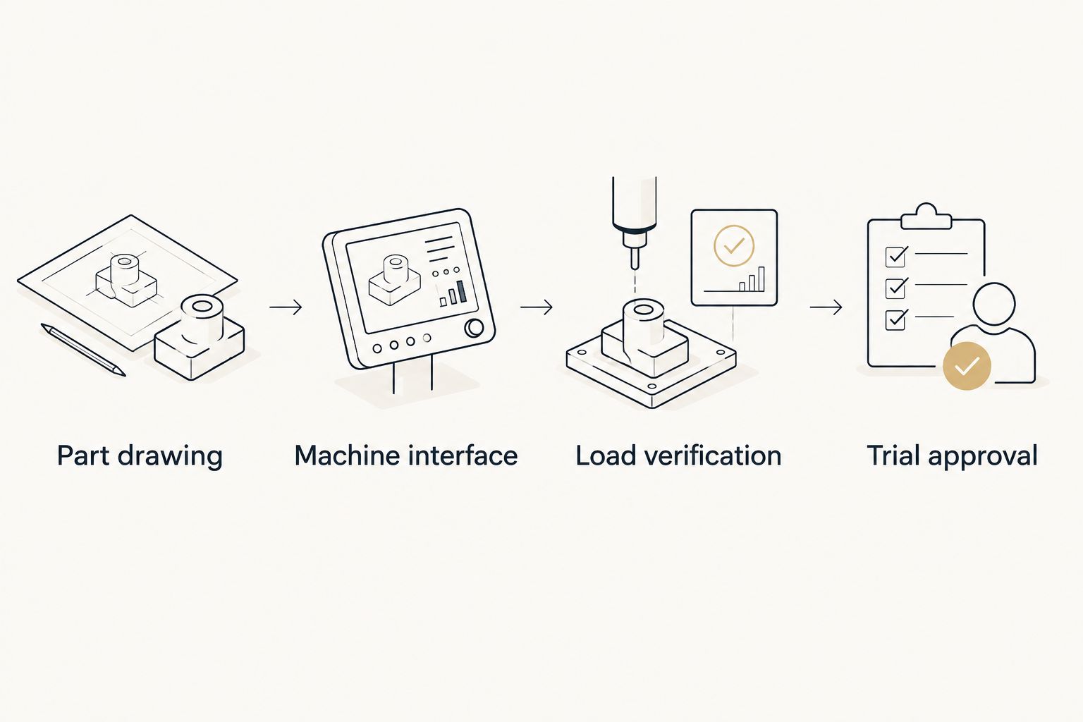
Machine interface and installed height
- Match the upper connection. Compare the punch tang, seating surfaces, clamping engagement and retention features with the actual holder drawing. Check the complete connection, including adapters. A machine brand or tooling-family name is not sufficient evidence of a fit.
- Match the lower connection. Verify the die base, locating features, support surfaces and retention arrangement against the lower holder. Confirm that the die sits on the intended load-bearing surface rather than on a locating feature or an unintended shoulder.
- Verify the installed assembly. Establish the upper and lower installed heights using the machine's documented reference convention. Include every adapter and support component. Check the required opening, available stroke and part-removal clearance against the complete assembly.
- Check segments and alignment. Verify segment lengths, joint positions and support across the working bend length. Establish alignment using the machine and tool supplier's approved method. Keep joints away from locations prohibited by the tooling documentation.
Expected result: The assembled punch, die and holders have a documented seating, retention and height relationship. The part can enter and leave the permitted working envelope without relying on an assumed dimension.
Do not machine a tang, alter a retention feature or add an unapproved spacer to resolve a mismatch. Stop and request a matched interface drawing. Chinacovo's custom press brake tooling review should receive the actual clamp and holder information, not only the press brake model designation.
Load verification and machine setup
- Establish the operation-specific load. Obtain the required forming and closing loads from an approved engineering assessment for the specified material, thickness, hem geometry and bend length. Do not substitute an ordinary air-bending calculation for a hemming assessment.
- Check every component limit. Compare the assessed load with the applicable machine, punch, die, holder and adapter limits. Distinguish a total-force rating from a load-per-length rating. Follow documented restrictions on minimum engagement length and concentrated loading.
- Configure the documented tooling assembly. Enter the approved geometry and installed-height information using the control instructions for the exact machine. Confirm the controller's reference definitions before entering values. Do not treat a familiar field name on another control as an equivalent setting.
- Configure the approved operation sequence. Set the required positioning, approach, forming and return behavior according to the machine and tool instructions. Verify any moving tooling elements using their own documentation. Keep machine guarding and protective systems active as required by the approved procedure.
Expected result: The setup has an approved load basis and a machine program that represents the actual tooling and operation. No component depends on the machine's overall capacity as a substitute for its own rating.
Keep the 2026 setup record explicit about force units and length units. Record dimensions in the drawing's specified system, and label force values with the units used by the machine and tooling documentation. Convert values deliberately; never copy an unlabeled value between records.
Controlled trial and production release
- Install under the prescribed safety procedure. Isolate the machine as required for installation, clean the intended seating surfaces and secure the tooling using the manufacturer's method. Inspect clamping engagement and retention before returning the machine to its permitted operating state.
- Verify clearance before forming. Use the machine's approved setup or simulation procedure to check the complete sequence. Inspect the flange, neighboring bends, backgauge fingers and part-removal path. A collision-free opening position does not establish clearance during closing.
- Run the approved sample. Use material representative of the production specification. Follow the documented trial procedure and observe the applicable force limits. Stop for interference, abnormal movement, incomplete seating or unexpected loading; do not compensate by increasing force.
- Inspect and release. Compare the sample with the finished-part criteria. Check the hem cross-section, flange position, edge condition, surface marking and adjacent bends. Release production only after the responsible personnel approve the setup and record the resulting program and tooling identification.
Expected result: A verified sample meets the drawing requirements, and the recorded setup can be reproduced without reconstructing decisions from operator memory.
Retain the accepted sample or its inspection record with the tooling assembly details. In a 2026 production release, identify the drawing revision, material specification and approved sequence together. A visually similar replacement tool still needs the relevant interface, height and load checks.
Variant: closing an already pre-bent flange
An already pre-bent flange changes the workflow. Approve the pre-bend as an input condition before assessing the closing operation. Its angle, radius and position determine how the flange contacts the closing surfaces.
- Define the acceptable pre-bend geometry and material condition on the process documentation.
- Confirm that the closing tool is intended to accept that geometry and produce the required final hem.
- Verify support and clearance through closing, including neighboring bends and the finished return edge.
- Inspect the incoming pre-bend separately from the finished hem during the trial.
The benefit is a separate verification point between forming and closing. The limitation is that variation from the pre-bend transfers into the closing operation. Do not describe this route as single-stroke forming from a flat blank; document both operations and their acceptance criteria.
Troubleshooting
The tool fits the clamp but the opening is insufficient
Recheck the complete installed-height stack, including adapters and lower supports. Compare it with the machine's documented working envelope. Do not remove structural components or modify tool seating to recover clearance without an approved redesign.
The flange collides during closing
Review the part through the entire forming sequence, not only at entry. Check nearby bends, tool shoulders and locating equipment. Revise the approved bend order or request a tooling geometry review rather than forcing the part through interference.
The hem is uneven along the bend length
Inspect seating cleanliness, segment alignment, part location and incoming flange geometry. Review the machine's documented parallelism and deflection-compensation procedures where applicable. Establish the source of variation before changing the closing setting.
The edge cracks or the surface marks
Check material grade, thickness, edge condition, forming radius and the approved hem cross-section. Inspect tool contact surfaces for damage or contamination. Do not assume that a deeper closing stroke corrects a material or geometry problem.
The closing operation approaches a load limit
Stop and verify the operation-specific load assessment, working length and component ratings. Review whether the selected process requires a different tool or sequence. An incomplete hem is not permission to exceed a documented limit.
Customize your workflow
Build the next tooling request around the finished part rather than an isolated punch or die. Send the part drawing, material specification, thickness, bend length, machine interface, installed-height references and required hem geometry. Add the proposed sequence and the current clearance constraint.
For Chinacovo custom press brake tooling, that package gives the engineering review a defined starting point. Check the tooling models to CAD-ready files workflow when preparing assembly geometry for clearance review. A model supports verification; it does not replace rated-load documentation or an approved trial.
Prepare your tooling review
Gather the part drawing, machine interface, material specification and required hem geometry.
FAQ
Can I connect COVO hemming tools to any one-hit hemming brake?
Compatibility requires a verified match between the tool and the actual machine assembly. Check the clamping interface, retention, installed height, working envelope and operation-specific load before installation.
Does one-hit hemming always mean one stroke from a flat blank?
No; the term alone does not establish the forming sequence. Confirm whether the documented tool accepts a flat blank, requires a pre-bent flange or uses separate operations at a combined station.
What specifications should I send for a custom hemming tool review?
Send the finished-part drawing, material grade, thickness, bend length, radius, flange geometry and required hem cross-section. Include the machine interface drawings, installed-height references and proposed forming sequence.
Can I use an air-bending force calculation for hem closing?
Do not use an ordinary air-bending calculation as the approval basis for hem closing. Obtain an operation-specific assessment and compare it with the limits of every load-bearing component.
Is a flat hem interchangeable with a teardrop hem?
No; flat and teardrop hems have different finished cross-sections. Select the tooling and closing sequence against the drawing's required gap, radius and edge geometry.
What should I do if a hemming tool fits but the installed height is wrong?
Stop and verify the full assembly against the machine's working envelope. Include adapters and supports, then request an approved interface or tooling revision rather than adding an undocumented spacer.
How do I approve a hemming setup for production?
Approve a representative trial against the finished-part drawing and inspection criteria. Record the tooling assembly, machine program, material specification and forming sequence so the accepted setup can be reproduced.
One last thing
Part removal belongs in the tooling review. A setup can have enough clearance to form a hem yet trap the finished return edge against the tooling or an adjacent flange. Verify the withdrawal path with the finished geometry before approving the setup; a successful closing stroke is not a complete process.
Related guides
- Connect tooling to a WILA clamping system
- Press brake dies for thin-gauge sheet metal
- Sheet metal hemming tools for aluminum panels
Open this COVO engineering guide · Browse press brake tooling · Request technical support