COVO KNOWLEDGE
How to connect COVO tooling to an LVD press brake
Published:
Updated:
LVD press brake tooling compatibility requires verified fit, retention and loads. Check interfaces, installed height and bend geometry before releasing a setup.
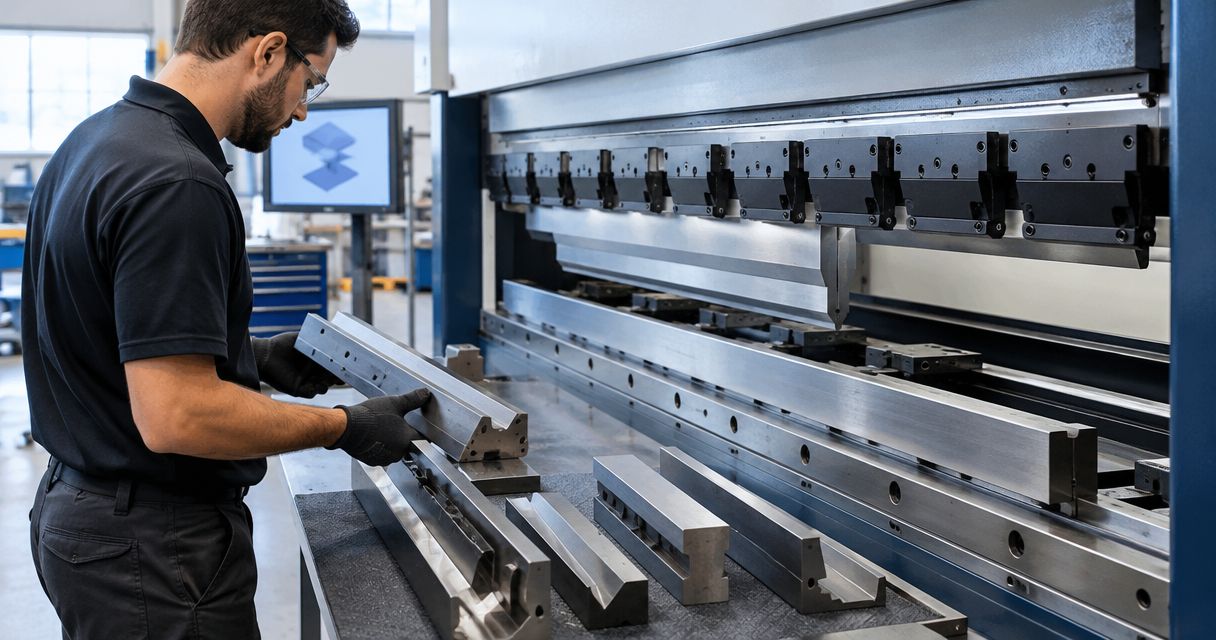
Instead of rechecking tool fit at every changeover, establish LVD press brake tooling compatibility by matching the punch and die interfaces, installed height, working geometry and load limits to your machine. Build an approved setup record for COVO tooling so each repeat job starts from verified drawings rather than a machine-brand assumption.
- LVD press brake tooling compatibility requires matched clamping interfaces, installed height, retention and load limits—not just an LVD label.
- COVO manufactures standard and custom press brake tooling; submit machine-interface drawings and finished-part geometry for tooling review.
- Verify punch and die interfaces separately before installation, then check bend clearance and the complete load path.
- Release a repeatable setup only after an authorized trial confirms fit, retention and finished-part dimensions.
Why this matters
A punch that enters the holder is not automatically an approved tool. Seating, retention, centerline alignment and load capacity must agree with the actual holder, lower support and bending operation.
COVO press brake tooling is suited to fabricators requesting standard or custom tools against a defined machine interface and finished-part drawing. The limitation is equally important: the manufacturer's tooling range does not establish compatibility with your particular LVD configuration.
Use the LVD-compatible press brake tooling supplier guide alongside this installation workflow. Supplier selection and machine setup are separate decisions; approve the physical interface before releasing a tool for production.
Before you start
- Machine access: Have the machine identification, current operating instructions, upper-holder and lower-support documentation, and access to an authorized setup operator. Follow the machine's prescribed isolation, tool-handling and safeguarding procedures.
- Engineering package: Assemble the finished-part drawing, material grade, thickness, bend length, radius, flange geometry and surface requirements. Include dimensioned punch, die and interface drawings—not photographs alone.
- Hidden gotcha: Confirm the installed holder configuration rather than relying on the LVD nameplate. Replacement holders, adapters and support arrangements change the interface and installed-height calculation; resolve those details before requesting tools.
For a 2026 tooling request, prepare 1 machine-configuration record, 2 interface drawings—upper and lower—and 1 finished-part drawing. These are document requirements for this workflow, not machine specifications. Record dimensions in mm and distinguish total force in kN from tool loading expressed in kN/m; convert source documents consistently before comparing limits.
Machine-interface verification
Treat the upper clamping interface and lower support as separate engineering checks. Matching the punch does not establish that the die seats correctly, and matching both interfaces does not yet establish bending suitability.
- Identify the installed configuration. Record the machine designation, holder identification, lower support and any intermediate components. Photograph the seating surfaces and retention features, then match them to dimensioned documentation.
- Compare the upper interface. Check the punch tang, seating shoulders, retention feature, insertion direction and clamping contact surfaces against the holder requirements. Verify the permitted installation and removal method in the actual operating instructions.
- Compare the lower interface. Check the die base, locating features, support width and attachment arrangement. Confirm that the intended die orientation places the working groove on the required bending centerline.
- Resolve mismatches before installation. Request a matching tool interface or an engineering-reviewed adapter arrangement. Do not grind a tang, remove a retention feature or force a component into the holder to obtain fit.
Expected result: You have an interface match supported by drawings, with a documented seating and retention method for both tools. A tool that merely slides into place has not passed this check.
Choose the connection route
Select the route from the documented mismatch—not from a familiar tooling-system name. The following alternatives describe engineering approaches, not confirmed configurations for every LVD machine.
| Connection route | Best for | Advantage | Limitation to verify |
|---|---|---|---|
| Direct-fit standard tooling | Jobs whose interface and working profile match an existing tool drawing | Avoids an additional adapter interface | Standard geometry must still meet radius, flange and clearance requirements |
| Custom-interface or custom-profile tooling | Parts or holders that require geometry outside the selected standard drawing | Allows the tooling request to address the specific interface or part constraint | Requires an agreed drawing and application review before release |
| Engineering-reviewed adapter arrangement | A documented tool-to-holder mismatch with a suitable adapter solution | Connects otherwise different interfaces when approved | Adds interfaces and changes installed height, clearance and load-path checks |
Choose direct fit when every required check passes; choose custom engineering when the drawing identifies a specific mismatch. An adapter is not a shortcut around retention or load verification.
Tool-stack and bending configuration
Interface fit answers whether the tools connect. This stage answers whether the connected tooling can perform the specified bend without exceeding the approved geometry or loading conditions.
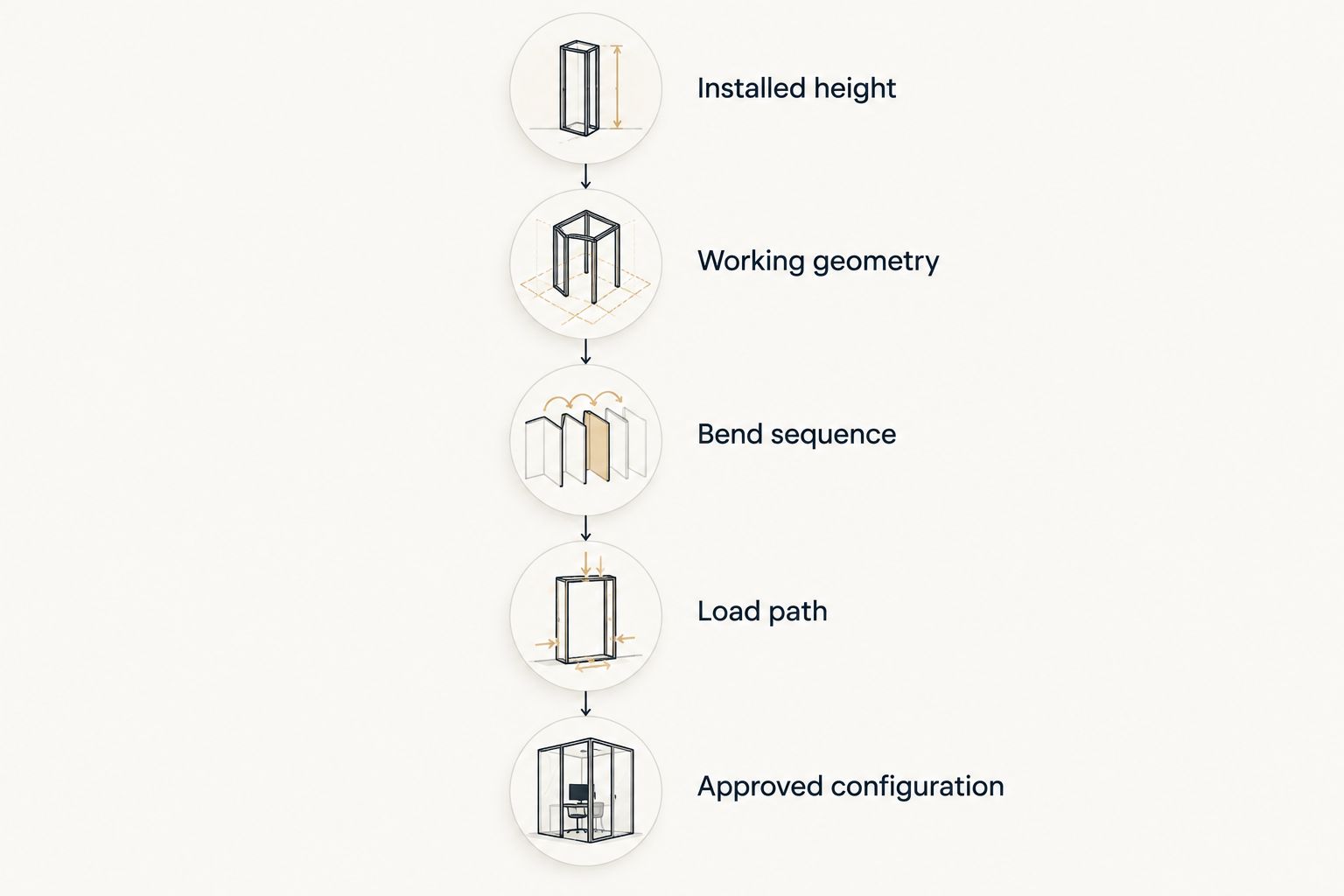
- Establish installed height. Calculate the assembled upper and lower tool stack from the defined reference surfaces, including holders and adapters where applicable. Use the same reference convention as the machine documentation; do not substitute a catalog tool height for the assembled stack.
- Check working geometry. Compare punch angle and tip radius, die opening and shoulder geometry with the material, thickness, target radius and flange geometry. Identify the intended bending method before calculating settings or required force.
- Check the complete bend sequence. Review approach, forming and withdrawal clearance for every bend. Include previously formed flanges, backgauge access, segmented-tool joints and the space needed to remove the finished part.
- Verify the load path. Compare the required bending load with the applicable machine, holder, adapter, punch, die and support limits. Use the actual engaged bend length, loading distribution and permitted working position; do not compare unlike total-force and force-per-length values.
- Record the approved configuration. Enter the verified tool geometry into the machine's tool-definition process using its actual operating instructions. Confirm reference surfaces and units before using the definition in a bending program.
Expected result: The proposed tool stack has an agreed installed height, working geometry, clearance envelope and permissible loading basis. In the 2026 setup record, keep interface approval separate from bending approval so one cannot be mistaken for the other.
A machine tool library is a record of geometry, not proof that the physical tool matches it. Keep the approved drawing revision with the tool definition, and confirm the installed tooling against that revision during setup.
Installation and trial-bend release
Only authorized personnel should install and commission press brake tooling. Use the machine and tooling instructions for isolation, lifting, insertion, clamping, seating and retention; do not replace those instructions with a generic control sequence.
- Prepare the seating surfaces. Inspect the holder, punch tang, die base and support for debris, burrs, wear or damage. Stop if a defect prevents documented seating or requires repair.
- Install and retain the tooling. Follow the prescribed handling and clamping procedure for the actual holder. Verify each segment's seating and retention, and confirm that the installed segment arrangement matches the approved bend-length plan.
- Verify alignment and clearance. Follow the machine's approved setup procedure to confirm punch-to-die centerline alignment and tool-stack position. Review the programmed movement and part clearance before authorizing a trial.
- Run the authorized trial. Use the approved bending method, material and program with the required safeguards active. Measure bend angle, radius where specified, flange dimensions and surface condition against the finished-part drawing.
- Release the setup record. Record the accepted tool arrangement, drawing revisions, material specification and approved settings. Document adjustments rather than leaving the next operator to reconstruct them.
Expected result: The installed tool stack is retained and aligned, and a trial part satisfies the agreed drawing requirements. Do not release the setup because the tools fit or because the first bend looks acceptable.
Keep the 2026 trial record tied to the material and tooling revisions used. A successful trial on one material specification does not approve a different grade, thickness or bend sequence.
Reverify tooling when a job or holder changes
A repeat job needs a change check, not an automatic restart. Compare the new requirement with the approved configuration before reusing a program or tool arrangement.
- Material change: Review grade, thickness, bending-force calculation, radius requirements and springback compensation. Confirm that the approved tooling limits still cover the revised operation.
- Part change: Review flange geometry, bend length, bend sequence, tool clearance and removal clearance. A revised return flange can create interference even when the tool interfaces remain unchanged.
- Holder or adapter change: Repeat interface, retention, installed-height and load-path verification. Do not retain the old tool definition solely because the punch profile is unchanged.
- Segment arrangement change: Check segment fit, working-length coverage, joint position, seating and the permitted loading distribution.
For a custom request, use the custom press brake tooling guide for OEM fabricators to organize the application details. COVO press brake tooling review should start with the finished-part drawing, machine interface, material grade, thickness and required geometry—not a request to copy a tool's appearance.
Expected result: Each change either stays within the documented approval or triggers a defined recheck. Mark revised 2026 records clearly so obsolete interface drawings and setup sheets do not return to the machine.
Prepare a tooling review request
Provide interface drawings, the finished-part drawing, material grade, thickness and required bend geometry.
Troubleshooting
The punch enters the holder but will not seat or retain
Stop installation and compare the tang, shoulder and retention feature with the holder drawing. Check for debris or damage only under the prescribed safe setup conditions. Do not treat partial engagement as acceptable clamping.
Tool contact differs from the programmed position
Check the installed-height references, units, adapter inclusion and tool-definition revision. Confirm that the physical punch and die match the selected geometry. Correct the underlying definition through the approved setup process before making another trial.
Flanges collide during forming or withdrawal
Review the complete bend sequence and tool envelope, including previously formed flanges. Check punch-body clearance, die support, segment arrangement and part-removal space. A profile change requires a renewed geometry and load review, not just a replacement punch.
Bend angle varies along the part
Verify material consistency, seating, alignment and the machine's approved compensation settings. Compare the actual bend length and loading position with the approved setup. Do not increase force as a substitute for finding the cause.
The interface fits but the load check fails
Identify which component limits the configuration and confirm that the ratings use comparable units and loading conditions. Review the bending method or tooling geometry through engineering. Physical fit never overrides a component's permitted load.
Customize your workflow
Build a setup packet that an operator can verify without interpreting an email chain. Include interface drawings, approved tool profiles, segment arrangement, installed-height references, the bending-load calculation, clearance review and trial acceptance criteria.
Separate machine approval, tool approval and part acceptance in the packet. The machine record identifies the installed hardware; the tool record identifies the approved geometry and limits; the part record defines the dimensions and surface requirements that the trial must satisfy.
For 2026 production records, make each revision traceable to the change that required it. Keep superseded records out of the active setup packet, and require reapproval when the holder, material or working geometry changes.
FAQ
How do I confirm LVD press brake tooling compatibility?
Confirm compatibility by matching the actual upper and lower interfaces, retention method, installed height, working geometry and load limits. Then complete an authorized installation and trial-bend check against the finished-part drawing.
Can I install COVO tooling on any LVD press brake?
Do not assume universal fit between COVO tooling and LVD press brakes. Compare the selected tool drawings with the machine's installed holders and lower support before installation.
Does a punch that fits the holder count as compatible?
No: insertion alone does not establish compatible seating, retention or loading. Verify the complete interface and then check the tool stack against the intended bending operation.
Do I need an adapter for LVD tooling?
An adapter is required only when an approved connection arrangement calls for one. Direct-fit tooling avoids that additional interface, while an adapter requires renewed installed-height, clearance, retention and load checks.
What drawings should I send for a custom tooling review?
Send the finished-part drawing and dimensioned upper and lower interface drawings. Include material grade, thickness, bend length, required radius, flange geometry and the installed holder configuration.
Can I reuse the same program after changing tooling?
Reuse the program only after verifying that its tool definitions and movement remain correct for the replacement tooling. Recheck installed height, working geometry, clearance and load limits before authorizing a trial.
What should I do if the first trial bend misses the angle?
Check the material specification, selected tool geometry, seating, alignment and approved program settings before adjusting the process. Follow the machine's prescribed trial procedure and record accepted corrections in the setup packet.
One last thing
Installed height belongs to the assembled stack, not just the punch. An unchanged working profile can require a different machine definition when the holder or adapter changes. Put the reference surfaces on the setup drawing; that prevents a familiar-looking tool from carrying an outdated height into production.
Related guides
- WILA-compatible press brake tooling options
- Segmented press brake dies for box forming
- Press brake tooling for electrical enclosures
Open this COVO engineering guide · Browse press brake tooling · Request technical support