COVO KNOWLEDGE
How to set punch-to-die clearance for sheet metal bending
Published:
Updated:
Set punch to die clearance by bending method, material and tool geometry. Verify V-opening, alignment, installed height and loads before production.
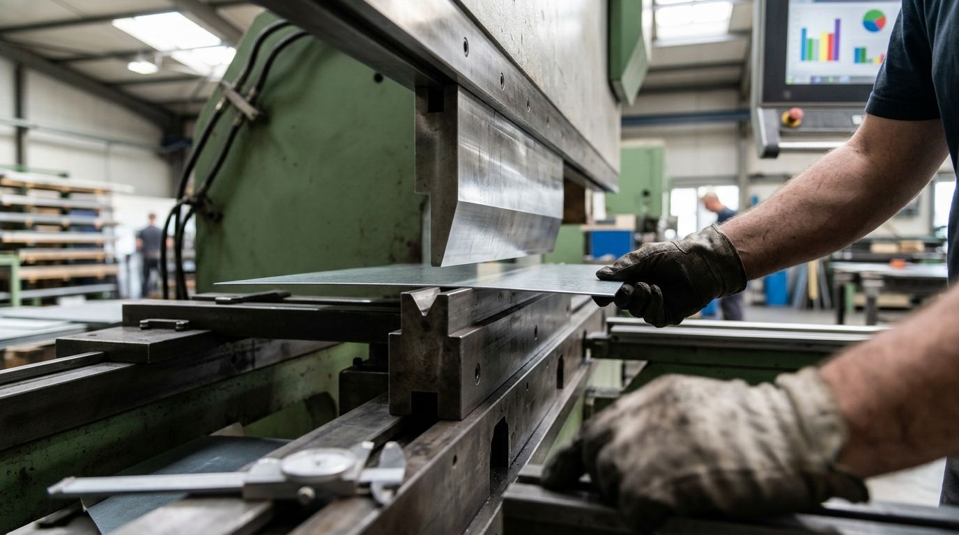
Set punch to die clearance for sheet metal bending by identifying the bending method, then checking the punch profile, die opening, material thickness and programmed penetration together. Air bending does not use the fixed per-side cutting clearance applied to punching or blanking. Verify tool alignment, working clearance throughout the stroke and load limits before proving the setup with a controlled trial bend.
- Punch to die clearance in air bending is not a fixed percentage of sheet thickness.
- Select the V-opening and punch radius together; verify flange support, penetration and tooling loads.
- Bottoming and coining require method-specific tooling review, not a deeper air-bending stroke.
- Chinacovo manufactures standard and custom press brake tooling for sheet metal fabricators.
Why this matters
A press brake setup can have adequate unloaded tool clearance and still fail during forming. The sheet occupies space, the flange rotates, and previously formed features move toward the punch, holder or machine structure.
Clearance is a full-stroke geometry check, not just a gap measured between unloaded tools. For your 2026 setup documentation, distinguish the die opening, punch penetration and part-to-tool clearance instead of recording a single ambiguous clearance value.
Start with the machine interface. The press brake tooling compatibility checklist addresses the separate fit checks needed before evaluating the working profiles.
How do you set punch to die clearance for sheet metal bending?
Use this sequence to establish a workable setup. Follow the machine manufacturer's setup and safeguarding procedures; never place hands between tools to check alignment or clearance.
- Identify the bending method. Confirm whether the operation is air bending, bottoming, coining or a special forming process. Each method creates a different contact condition between sheet and tooling.
- Verify the material. Record the grade, measured thickness, rolling direction where relevant, and specified inside radius. Use the material information required by the machine's bending database or an approved engineering calculation.
- Select the working profiles. Check the die V-opening, die angle, shoulder radii, punch tip radius and punch angle against the finished-part geometry. Confirm that the flange remains supported during the intended operation.
- Verify the machine interface. Check the clamping interface, retention, seating surfaces, installed height and permitted tool orientation. Compatible working profiles do not establish compatible mounting geometry.
- Check the forming envelope. Review punch penetration, open height, stroke, backgauge clearance and part rotation through the bend sequence. Include existing flanges and the holders, not just the punch tip and die opening.
- Verify loads and prove the bend. Compare the calculated requirement with the machine, punch, die and holder ratings. Under approved operating procedures, make a trial bend and measure the unloaded angle, radius and flange dimensions.
Keep these checks separate on the setup sheet. A correction to bend depth does not correct a misaligned die, an unsupported flange or an incompatible holder.
What changes between bending methods?
| Method | Best for | How clearance is evaluated | Advantage | Limitation |
|---|---|---|---|---|
| Air bending | Parts whose geometry suits depth-controlled bending | Check V-opening, punch penetration, sheet support and moving-part clearance | Different angles can be produced with suitable tooling by changing penetration | Material variation and springback affect the unloaded angle |
| Bottoming | Parts suited to matched tooling and the intended contact condition | Check the punch, die and material together at the specified forming position | Tool geometry helps establish the bend geometry | Requires method-specific profiles and load verification |
| Coining | Applications specifically engineered for localized compressive forming | Check the intended material compression, profiles and rated load | Can reduce springback through plastic deformation at the bend | High forming loads restrict suitable machines, tools and applications |
Do not transfer a punching-clearance formula to a press brake setup. Cutting clearance controls separation at cutting edges; bending requires space and support for material deformation.
Air bending: check the V-opening and penetration
In air bending, the sheet contacts the punch and the die shoulders without being fully pressed against the die faces. The programmed punch position controls the bend under load, while springback changes the angle after unloading.
The die V-opening is therefore not interchangeable with a per-side clearance dimension. A wider opening generally reduces the force required for otherwise comparable air-bending conditions, but also changes the resulting radius and flange-support requirements.
Check the following before adjusting depth:
- Does the selected opening support the required flange geometry?
- Is the expected inside radius acceptable for the drawing and material?
- Can the punch reach the required loaded angle without unintended contact?
- Are the die shoulders and punch tip suitable for the surface requirement?
- Does the load calculation use the actual bend length and selected opening?
For a 2026 air-bending setup record, identify the actual punch and die profiles rather than recording only the target angle. Prove the angle and radius together; an acceptable angle does not establish an acceptable radius.
Bottoming: verify the matched contact geometry
Bottoming brings the sheet into more extensive contact with the tooling than air bending. The punch profile, die profile and material thickness must suit the intended final contact condition.
Do not infer suitability from the tool angles alone. Verify the punch tip radius, die geometry, material thickness and stroke endpoint using the tooling supplier's method-specific guidance.
A setup that reaches the target angle during air bending is not automatically suitable for bottoming. Continuing the stroke changes the contact condition and load demand; it is not simply another angle correction.
Use bottoming only with verified profiles and loads. If the setup documentation does not identify the intended process, resolve that question before programming the forming position.
Coining: verify compression and capacity
Coining uses localized compressive deformation at the bend. It requires an engineered tooling and machine combination, not an assumed clearance taken from an air-bending chart.
Check the material, intended geometry, contact area and required forming load against the ratings of the entire load path. Include the punch, die, holders and machine rather than treating machine capacity as the only limit.
For your 2026 coining setup, keep the approved process conditions with the tooling identification. Do not use additional penetration as an unverified remedy for springback. Stop and review the process when the required angle cannot be achieved within the approved conditions.
Why punch-to-die clearance requirements vary
The relevant geometry changes with the part, material and bending method. These factors determine what you need to verify:
- Material grade and thickness: Strength, ductility and thickness affect forming force, springback and achievable bend geometry. Confirm the actual stock rather than relying on an unspecified gauge designation.
- Inside radius: The required radius constrains tool selection. Check the radius produced by the selected process rather than assuming the punch tip radius always becomes the finished inside radius.
- Flange geometry: Short flanges need sufficient die support; return flanges need space around the punch body and holder. Include the complete bend sequence.
- Die opening and shoulders: Opening width affects support, force and air-bent radius. Shoulder geometry also affects contact with the sheet surface.
- Punch profile and installed height: Tip geometry controls local contact, while the punch body determines clearance around formed features. Installed height affects the available working envelope.
- Bend length and loading: Total force and permitted local loading must both be checked. A short loaded section can exceed a tool's permissible loading even when total machine capacity is adequate.
Record the controlling factor for each bend. That makes later troubleshooting more useful than a note saying only that clearance was adjusted.
How do you check alignment before a trial bend?
Check alignment using the machine and tooling manufacturers' approved procedure. Inspect seating surfaces, confirm that tooling is fully seated and retained, and verify the punch position relative to the die along the working length.
Debris, damaged seating surfaces or inconsistent segment seating can disrupt alignment. Correct those conditions before changing the program; a depth adjustment cannot restore a mechanical reference.
Also check whether the intended bend loads the tool arrangement centrally or eccentrically. Follow the permitted loading conditions for the machine and tooling, especially when using short segments or offset features.
What should you measure after the first bend?
Measure the unloaded bend angle, inside radius and flange dimensions against the finished-part drawing. Inspect surface marking, cracking and distortion as well as dimensional acceptance.
If the angle is wrong but the radius and support are acceptable, review the approved angle-correction procedure. If the radius, flange support or collision clearance is wrong, review the tool selection and sequence rather than treating penetration as the only variable.
Change one setup variable at a time where practical. Record the change and result so your 2026 production setup preserves the verified conditions rather than an unexplained final ram position.
What should you send for a tooling review?
Send the finished-part drawing together with the machine interface and material specifications. A part drawing alone does not establish whether a tool fits the holder or clears the machine during forming.
Use this submission checklist:
- Finished-part drawing and revision, including angle, radius and dimensional tolerances.
- Material grade, measured thickness and relevant surface requirements.
- Bend length, flange geometry, return features and proposed bend sequence.
- Machine model, clamping interface, holder details and available working envelope.
- Existing punch and die drawings, installed height and segment arrangement.
- Intended bending method and applicable machine and tooling load limits.
Chinacovo press brake tooling is best for fabricators seeking standard or custom punches and dies reviewed against part and machine requirements. Chinacovo manufactures both standard and custom forming tools; selecting either still requires verification of the interface, geometry and loading.
For a custom press brake tooling review, give Chinacovo the required finished geometry rather than prescribing an isolated clearance value. That keeps the review focused on whether the complete tooling arrangement can form the part.
FAQ
What is the correct punch to die clearance for sheet metal bending?
There is no single punch to die clearance that applies to every press brake bending operation. Identify the bending method, then verify the die opening, punch profile, material thickness, penetration and full-stroke clearance together.
Can I use punching clearance for press brake bending?
No. Punching clearance concerns the gap between cutting edges, while press brake bending depends on tool contact, sheet support and deformation throughout the stroke.
Is the die V-opening the same as punch-to-die clearance?
No. The V-opening is a die dimension, not a fixed per-side gap around the punch. Its suitability depends on the bending method, material, required radius and flange support.
Does the punch radius always equal the finished inside bend radius?
No. In air bending, the finished inside radius depends on the material and die opening as well as the tooling contact conditions. Verify the actual radius on the trial part.
Should I increase penetration when the bend springs back?
Adjust penetration only within an approved bending setup and load limit. First verify the material, selected method and tooling; additional penetration can change the contact condition and increase loading.
What should I check before ordering replacement punches and dies?
Check the clamping interface, retention, installed height, working profiles, segment arrangement and rated loads. Provide the finished-part drawing, material grade, thickness and required bend geometry for review.
Can a press brake have enough total capacity but still overload a tool?
Yes. Local tool loading can exceed the permitted rating even when total force remains within machine capacity. Check the manufacturer's loading limits for the actual loaded length and arrangement.
One last thing
A part can clear the punch at the finished angle and still collide during rotation. Check the entire movement, including loading, bending, repositioning and removal—not just the final cross-section.
Before releasing your 2026 setup, retain the verified tooling identification, material specification, bend sequence and inspection results together. The useful output is a repeatable forming setup, not a clearance number separated from the conditions that made it work.
Related guides
- Minimum flange length benchmarks by V-die opening
- Minimum bend radius benchmarks by material and thickness
- How to inspect press brake dies for wear before reordering
- Can you mix press brake punches and dies from different brands?
Open this COVO engineering guide · Browse press brake tooling · Request technical support