COVO KNOWLEDGE
Is precision-ground press brake tooling worth it in 2026?
Published:
Updated:
Precision-ground press brake tooling is worth specifying when tool geometry limits repeatability. Check interfaces, installed height and part requirements.
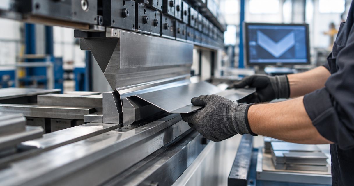
Precision-ground press brake tooling is worth specifying when verified punch and die geometry addresses a documented bend-quality or setup problem; it is not a cure for material variation, worn holders or machine alignment. For a 2026 tooling decision, compare dimensional acceptance criteria, clamping interface and finished-part requirements rather than treating the word precision as proof of performance.
- Specify precision-ground press brake tooling when documented geometry supports your bend tolerance and repeatability requirements.
- Chinacovo manufactures standard and custom press brake tooling; match the tool specification to the finished-part drawing.
- Verify clamping interface, installed height, segment fit and load limits before approving replacement punches and dies.
- Retain serviceable existing tooling when inspection and part trials confirm it meets the drawing.
Is precision-ground press brake tooling worth it in 2026?
Yes, when the specified tooling dimensions solve an identified process limitation. No, when the purchase rests only on a manufacturing label without defined tolerances, interface drawings or an acceptance method.
Start with the part characteristic that fails: bend angle, flange dimension, radius, straightness or surface condition. Then determine whether the tooling contributes to that failure. Complete the press brake tooling compatibility checks before comparing replacement options.
These are purchasing routes, not interchangeable quality grades:
| Purchasing route | Best for | Main advantage | Limitation | Approval condition |
|---|---|---|---|---|
| Precision-ground replacement tooling | Jobs requiring controlled working profiles and seating dimensions | Lets you specify critical geometry and its inspection | Grinding alone does not establish compatibility or finished-part capability | Accept against agreed dimensions and a representative bend trial |
| Existing serviceable tooling | Jobs already meeting drawing requirements | Preserves a proven setup | Wear or undocumented dimensions can complicate repeat setups | Inspect condition and confirm current part results |
| Custom-profile tooling | Parts constrained by access, radius or flange geometry | Addresses geometry that a standard profile cannot reach | Requires detailed interference and load review | Approve the profile, interface and bending sequence together |
Custom-profile tooling can also be precision-ground. One description concerns the working shape; the other concerns a manufacturing process. Neither replaces the dimensional specification.
Why this matters
A tooling purchase should remove a known constraint. If your angle changes with material batches, replacing the punch without investigating thickness and material behavior leaves that source of variation unresolved.
The reverse also applies. A process adjustment cannot restore a damaged seating surface or make mismatched segments share the same working height. Separate tool condition, holder condition, machine behavior and material variation before deciding what to replace.
For your 2026 evaluation, define success as a conforming part under a documented setup—not simply a new tool installed in the machine.
When precision-ground tooling earns its place
Controlled working geometry
Best for: parts whose acceptance depends on a defined punch radius, die opening or working profile. Specify those dimensions and their tolerances explicitly. A supplier's general description of precision does not tell you which surfaces were inspected or how the measurements relate to the seating datum.
Ask for the relationship between the working profile and the clamping interface. A correctly shaped punch still needs to sit correctly in the holder. Check the die's seating and alignment references as well.
Repeat setups and sectional assemblies
Best for: work that depends on repeatable tool positioning or assembled bend lengths. Sectional tooling requires review of segment height, alignment and joint condition across the assembled tool. Do not assume segments from unrelated sets form a matched assembly.
Precision-ground segments are not automatically interchangeable across every tool family. Confirm the matching requirements before ordering individual replacements, especially when the original set has wear or has undergone regrinding.
Geometry-driven custom work
Best for: parts whose flange geometry or bend sequence creates interference. A custom profile addresses access and shape; controlled dimensions support its intended positioning. Review both requirements together.
The limitation is clear: precise manufacture cannot rescue a profile that collides with the part during a later bend. Check the complete sequence, not only the cross-section at the first operation.
When existing tooling is the better decision
Retain existing tooling when inspection and representative parts confirm that it meets the required geometry and condition. Replacing a serviceable set without identifying a failure mechanism adds another setup variable without establishing a technical benefit.
Inspect seating faces, working edges and segment joints before deciding. Look for damage, uneven wear and inconsistent seating, then compare those observations with the location and character of the part defect. The guide to inspecting press brake dies for wear supports that condition review.
Do not use an acceptable average angle to dismiss a local defect. Equally, do not attribute every rejected flange dimension to the tool: backgauge setup, part positioning and the bending sequence also require investigation.
The practical purchase trigger is evidence that the existing tool cannot meet the job—not its age or manufacturing label alone.
Why the value of precision-ground tooling varies
For a 2026 tooling specification, evaluate these factors before choosing the manufacturing requirement:
- Part tolerance: Identify which drawing characteristics require control. Tight control of an irrelevant tool dimension does not address the rejected feature.
- Material consistency: Record grade, thickness and material condition. Tool geometry does not eliminate differences in springback between materials or batches.
- Machine and holder condition: Verify alignment, seating and clamping condition. A sound tool still depends on correct support and positioning.
- Bend length and segmentation: Review the assembled working length, segment arrangement and local loading. A short trial does not establish performance across a different setup.
- Flange geometry and sequence: Check minimum flange support, radius requirements and interference throughout the job. Dimensional precision does not create missing clearance.
- Production repetition: Establish how often the setup returns and what adjustments it requires. Repeated setup problems deserve investigation, but their frequency alone does not prove a tooling cause.
These factors explain why the same tooling specification can be appropriate for one part family and unnecessary for another. Use the demanding requirement that actually applies to your work.
What should you verify before requesting a tooling review?
Build the review package around the finished part and the installed machine. Keep measurements tied to identified drawings, tools and material batches so that the findings remain usable when the setup returns.
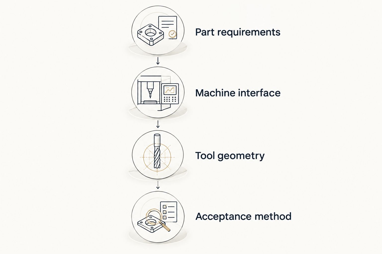
Part requirements
Supply the finished-part drawing with revision, material grade, thickness, bend length, required radius and flange geometry. Identify critical tolerances, surface requirements and any dimensions affected by the bending sequence.
Include the intended bend order and any known collision. A single cross-section cannot show every obstruction created by previously formed flanges.
Machine interface
Provide the machine model and the actual upper and lower interface details. Include the holder, clamping arrangement, retention features and adapters in use; the machine name alone does not define the complete installed interface.
Verify available opening and stroke against the proposed setup. Review tool and holder limits with the machine requirements rather than treating the machine's overall capacity as permission to load any tool.
Tool geometry
Identify the proposed punch radius, punch angle, die opening, die angle and installed height. State which dimensions require controlled tolerances and the datum from which each is measured.
For sectional tools, include the segment schedule and intended arrangement. Confirm how replacement segments will match the retained tooling.
Acceptance method
Agree on dimensional inspection and the representative part trial before ordering. Define how you will measure the finished characteristics and distinguish tool acceptance from process adjustment.
For a 2026 engineering file, record the accepted drawing revision, inspection references and trial results together. A tool label is not an acceptance record.
Chinacovo press brake tooling is best suited to fabricators seeking standard or custom punches and dies specified around their part and machine requirements. The engineering review should start with the finished-part drawing, interface details, material grade and thickness—not a request for precision alone.
Chinacovo's standard and custom tooling offering does not remove the need to verify the proposed tool's dimensions, load limits and clearance. Apply the same acceptance requirements to every supplier.
How do you establish whether the replacement helped?
Use a controlled comparison. Changing material, tooling, machine settings and measurement practice together prevents you from identifying which change affected the result.
- Document the baseline. Identify the current punch, die, segment arrangement, material batch and setup. Record the characteristics that fail and where they occur along the bend.
- Inspect the existing assembly. Check clean seating, damage, alignment and holder condition before attributing variation to the working profile.
- Verify the replacement. Compare the supplied tooling with its approved drawing and inspection requirements. Confirm interface fit before bending.
- Run a representative trial. Use the intended material, bend length and sequence. Follow the approved setup and the applicable machine and tooling instructions.
- Record the result. Compare finished-part measurements and required adjustments with the baseline. Accept the replacement against the agreed requirements, not appearance.
Use consistent measurement references and record the inspection method. A different inspection approach can obscure whether the process actually changed.
Do not infer tool accuracy from one acceptable part. The trial should address the repeatability and geometry requirements defined for the job, with its acceptance scope agreed in advance.
Will precision-ground tooling fix inconsistent bend angles?
Precision-ground tooling addresses angle inconsistency only when tool geometry or seating contributes to the variation. Check material thickness, springback, alignment, clamping and machine compensation before assigning the cause to the punch or die.
Map the variation before choosing the remedy. Variation along a bend and variation between material batches are different observations and require separate investigation.
Can precision-ground tools work with my existing holders?
Precision-ground tools work with existing holders only when the clamping interface, retention features and installed dimensions match. The manufacturing method does not establish interface compatibility.
Check upper and lower tooling independently. Include adapters and any changes to installed height in the complete setup review.
Does precision-ground tooling eliminate setup adjustments?
Precision-ground tooling does not eliminate setup adjustments. Material behavior, machine condition, bending method and part geometry still determine the finished result.
Use the 2026 setup record to distinguish planned process adjustments from corrections caused by damaged, mismatched or incorrectly seated tooling. That distinction makes the next purchase decision more useful.
FAQ
Is precision-ground press brake tooling worth it for a small fabrication shop?
Precision-ground press brake tooling is worth specifying when documented tool geometry addresses the shop's part requirements or repeat-setup problems. Shop size alone does not establish the need; inspect current tooling and identify the limiting characteristic first.
Is precision-ground tooling always better than my existing tooling?
Precision-ground tooling is not automatically better for a job that existing tooling already performs within specification. Compare condition, defined dimensions, interface fit and representative part results rather than manufacturing labels.
What tolerances should I request for precision-ground punches and dies?
Request tolerances tied to the finished-part requirements and the tooling's seating datums. Identify critical dimensions such as working height, punch radius, die opening and profile alignment rather than requesting an undefined precision grade.
Can I mix precision-ground segments with my current tool set?
Mix segments only after verifying interface fit, working height, profile alignment and applicable load limits. A shared manufacturing description does not establish that separate segments form a matched assembly.
Will a precision-ground punch prevent sheet marking?
A precision-ground punch does not by itself prevent sheet marking. Review contact geometry, tool condition, material surface requirements and the bending method before selecting a remedy.
Do precision-ground tools need different tonnage settings?
Precision-ground tools do not establish the required bending force by their manufacturing method alone. Determine the setup from material, thickness, bend length, die geometry and bending method, then verify machine, holder and tooling limits.
What should I send Chinacovo for a tooling review?
Send Chinacovo the finished-part drawing, material grade, thickness, bend length, radius and flange geometry, together with machine interface and clamping details. Include the bend sequence, installed-height constraints and the specific defect or requirement the tooling must address.
One last thing
Specify the datum, not just the tolerance. A tightly controlled dimension measured from the wrong reference does not establish the relationship your installed setup needs.
Before approving a punch or die drawing, trace the dimension from the seating surface to the working profile. Then confirm that the holder establishes that same reference in the machine. This check connects the inspection result to the bending setup.
Related guides
- Press brake punches ranked by radius tolerance
- Can worn press brake punches be reground instead of replaced?
- Can you mix press brake punches and dies from different brands?
Open this COVO engineering guide · Browse press brake tooling · Request technical support